Caster angle (caster) - the angle between the axis of rotation of the wheel and the vertical in the side view. It is considered positive if the axis is tilted back relative to the direction of motion.
Camber - the inclination of the wheel plane to the perpendicular, restored to the plane of the road. If the upper part of the wheel is tilted outward of the car, then the camber angle is positive, and if inward, then it is negative.

Convergence - the angle between the longitudinal axis of the car and the plane passing through the center of the tire of the steered wheel. Convergence is considered positive if the planes of rotation of the wheels intersect in front of the car, and negative if, on the contrary, they intersect somewhere behind.
The following are experiments that allow you to understand how wheel adjustments affect the behavior of the car.
The Samara VAZ-2114 was chosen for the tests - most modern foreign cars do not burden the owner with a range and choice of adjustments. There, all the parameters are set by the manufacturer and it is quite difficult to influence them without constructive alterations.
The new car has an unexpectedly light steering and slurred behavior on the road. The camber angles are within the tolerance range, with the exception of the longitudinal angle of inclination of the axis of rotation of the left wheel (caster). With regard to the front suspension of a domestic front-wheel drive car, setting angles always begins with adjusting the caster. It is this parameter, on the one hand, that determines the rest, and on the other hand, it has a lesser effect on tire wear and other nuances associated with the car's rolling. Moreover, this operation is the most time-consuming - I think that is why it is “forgotten” at the plant. Only then, having dealt with the longitudinal angles, a competent master begins to adjust the camber, and then the toe-in.
Option 1
The master maximally shifts the angles of the longitudinal inclination of the racks, taking them to the “minus”. We kind of move the front wheels back to the mudguards of the wheel wells. A situation that is quite common on old and heavily “left” cars or after installing spacers that raise the rear of the car. The result: light steering, fast responses to its slightest deviations. However, "Samara" has become overly nervous and fidgety, which is especially noticeable at speeds after 80-90 km / h and above. The car has unstable responses when entering a turn (not necessarily fast), strives to take risks to the side, requiring the driver to constantly steer. The situation becomes more complicated when performing the “rearrangement” maneuver.
Option 2
The "correct" position of the racks (tilted to the "plus"), set to "zero" and the angles of convergence and collapse. The steering wheel has become elastic and informative, and a little more "heavy". The car drives clearly, clearly and correctly. The fidgetiness, slurred relationships and trajectory yaws have disappeared. At the "rearrangement" VAZ easily outstripped the previous version.
Option 3
Overly "positive" collapse. It is undesirable to change it without correcting the convergence, therefore, a positive convergence is also introduced.
Again, the steering wheel became "lighter", the responses at the entrance to the turn became lazier, the lateral buildup of the body increased. But there are no catastrophic deteriorations in character. However, when modeling an extreme situation, the "rudder feeling" is lost. With the advent of slips, unexpectedly early, it becomes more difficult to get into a given corridor on the "rearrangement" and the car starts to slide too early. In fast corners, the strongest slippage of the front axle dominates.
Option 4
A variant with sporting ambitions: everything is in the "minus", except for the caster. A car with such settings turns more confidently and faster, as well as the “rearrangement” maneuver. Hence the best result.
So, there are many simple and very effective ways to change the character of the car without resorting to costly replacements of components and parts. The main thing is not to neglect the adjustments - they often turn out to be very important.
Which of the options to give preference? For most, the second will be acceptable. It is most logical for everyday driving, both with partial and full load. It is only necessary to take into account that by increasing the longitudinal inclination of the rack, you not only improve the behavior of the car, but also increase the stabilizing (return) force on the steering wheel.
The last, most “fastest” setting option is more suitable for the near-sports audience who loves to improvise with the car. Giving preference to these adjustments, it must be borne in mind that with increasing load, the values \u200b\u200bof the toe and camber angles will increase and may go beyond the permissible limits.
Ideally, the wheels should be strictly perpendicular to the road. In this case, maximum stability and minimum resistance to movement are ensured. Tire wear and fuel consumption are also minimized. But, as we know, the ideal is unattainable. The position of the wheels changes when the load changes, road conditions and when turning. Therefore, designers put into the car up to two dozen different parameters that determine optimal installation wheels under various driving conditions. Of these parameters, most are set as constant values, while some are subject to adjustment during operation. This is the well-known “camber” and the lesser-known caster. And in modern foreign cars, only one parameter is regulated at all - wheel alignment. But this seemingly positive circumstance also has back side. If, for example, as a result of an impact, the geometry of the chassis or body is slightly disturbed, then the position of the wheels on a “normal” car can be aligned by “playing” with angle adjustments. If only convergence is regulated, it is necessary to replace the affected (and quite expensive) parts.
"Angular" theory
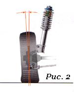
The angle of longitudinal inclination of the axis of rotation (caster (Caster)) (Fig. 1) is the angle between the vertical and the line passing through the centers of rotation of the ball joint and the bearing of the telescopic strut support, in a plane parallel to the longitudinal axis of the vehicle. It contributes to the stabilization of the steered wheels, that is, it allows the car to drive straight with the steering wheel released. To visualize what a caster is, think of a bicycle or a motorcycle. Them steering column tilted back. Because of this, in motion, the wheel constantly strives to take a straight position. It is thanks to the caster that when the steering wheel is released, the car drives straight, and when exiting the turn, it automatically returns the wheels to their original position. If the angle of inclination is reduced, the car becomes more difficult to control, you have to constantly steer, which is tiring for the driver, and the tires wear out faster. If you increase the caster, the car will drive along the road like a tank, but the rotation of the steering wheel will turn into an exercise in the gym. The above applies to a greater extent to rear wheel drive vehicles. In front-wheel drive, a small positive caster value is set to stabilize the wheels when coasting, braking, or when sudden side loads (wind) occur. Signs of a deviation of the angle from the norm: car pulling to the side while driving, different efforts on the steering wheel in left and right turns.
 Camber angle (Fig. 2) - the angle between the plane of rotation of the wheel and the vertical. To put it simply, no matter how the levers and racks tilt when driving or changing the load, the position of the wheel relative to the road must remain within the specified limits. If the top of the wheel is tilted outward, the camber is considered positive, if the wheel is tilted inward, the camber is negative. When the wheel camber deviates from the norm, the car spontaneously leads to the side, and the tire tread wears out unevenly.
 Toe-in (Fig. 3) - the angle between the plane of rotation of the wheel and the longitudinal axis of the vehicle. Wheel alignment contributes to the correct position of the steered wheels at various speeds and angles of rotation of the car. With an increased convergence of the front wheels, the outer part of the tread wears out strongly in a sawtooth manner, and with a negative angle, the inner part is subjected to the same wear. At the same time, the tires begin to squeal in turns, the controllability of the car is disturbed (the car “scours” along the road), fuel consumption increases due to the high rolling resistance of the front wheels. Accordingly, the run-out of the car is reduced. Convergence and collapse are interdependent quantities.
In addition to the listed angles, there are angles whose appearance is undesirable: the angles of movement and displacement of one or more axes. If available, the suspension or body of the car needs to be repaired.
 a - wheel shift (the defect occurs in operation due to deformation of the suspension elements
- b - deviation of the vehicle's thrust line (reason - operational);
- c - reverse (negative) convergence in a turn (measured as the difference in the angles of rotation of the inner and outer wheels, measured relative to the longitudinal axis; in case of violation, one of the steered wheels slips, which reduces stability when cornering).
When to Adjust and Should You Adjust?
During operation, natural wear of suspension parts occurs. As a result, the wheel alignment angles are violated. Therefore, periodically, as prescribed in the manual, it is necessary to carry out their control and, if necessary, adjustment. The car needs “unscheduled” adjustment most often after hitting obstacles or pits, as well as after accidents in which the body was damaged. If after such a case the behavior of the car has changed (beginning to “pull” to the side or it constantly has to be “caught” by the steering wheel on a straight line, the steering wheel is not in the middle position when driving straight, the steering wheel does not return to the middle position when exiting the turn, the tires wear out unevenly and squealing in the corners), then you should go to the service station without delay. And the third reason to call on the “razvalshchiki” is after replacing the suspension and steering parts that affect the position of the wheels.
If none of the above options occurred, and the symptoms of “wrong angles” appear, take your time and analyze the situation. What preceded the change in the nature of the ride? If, for example, other wheels were installed, then the vibrations and uneven wear tread can be caused by their imbalance. Shakes the car and with insufficient tightening of the wheel bolts. Defective, mismatched, mismatched tread patterns, and underinflated tires will also cause the vehicle to behave abnormally. Pulling the machine to the side may be the result of braking one of the wheels due to a malfunction brake mechanism. And faulty shock absorbers provoke unstable behavior on the road. Is the steering wheel hard to turn? It is possible that the hydraulic booster is to blame. Decreased runout? Wheel bearings could be the cause.
Where to do and what to do
The first rule is to look for an intelligent, conscientious master, and not a "fancy" stand. Second, choose a service based on your needs. If, for example, the car is in good condition and you only want to check and adjust the toe-in, you don't need a 3D stand for this. A good specialist will cope with the help of a lift and a measuring rod. With the same result, the difference in price will be very noticeable. But if you need a thorough check of the entire "geometry", here you can not do without the appropriate equipment. Stands for monitoring and adjusting wheel alignment angles can be divided into two large groups: optical and computer.
Optical stands are beam and laser. In beam light source is an incandescent lamp. Two such sources (collimators) are attached to the wheels, and measuring screens (targets) are placed in front and on the side of the car, onto which a beam of light is projected. When adjusting the convergence, the beams are directed to a measuring rod located in front of the machine. Laser stands are more accurate and easier to work with. Measuring screens are installed on the sides of the pit or lift. Holes are made in their centers through which laser beams are directed strictly towards each other. Mirrors are attached to the wheels of the car, from which the rays are reflected on the screens. The advantages of optical stands include simplicity and the resulting reliability. They also differ in low price. But the disadvantages are much more significant - relatively low accuracy, the ability to work simultaneously with only one axis of the car, the lack of a database of models and the inability to measure some parameters (for example, turning rear axle) that characterize the overall "geometry" of the vehicle. If the car has multi-link suspension, optical stands are contraindicated for him.
Computer stands are divided into sensor (CCD) and 3D. In the first, interconnected measuring heads are attached to each wheel, the information from which is processed by a computer. According to the method of connection between the heads, the stands are corded (a rubber band is pulled between the heads, and the connection to the computer is via a cable), infrared wired (connection between the heads is provided by means of infrared rays, and with the computer through a cable) and infrared wireless (the heads are connected to the computer via a cable). radio channel). The last type of stands is by far the most common. When choosing, keep in mind that there are still open-loop (two measuring heads) computer stands that are much less functional than closed-loop (four-head) stands.
The advantages of computer stands are obvious: high accuracy, the ability to work with two axes at once and measure many more parameters, the presence of a constantly updated database (about 40 thousand models), a program that tells the mechanic the sequence of actions. But CCD stands are not without drawbacks - fragile sensors, dependence on temperature conditions, illumination. They require periodic checks and adjustments (twice a year).
The emergence of computer 3D stands, many experts call a revolution in the field of control and adjustment of wheel alignment. As they say, ingenious is always simple. On the rack in front of the car, video cameras are fixed, which with highest precision fix the position of the plastic reflective targets fixed on the wheels. To measure angles, it is enough to roll the car 20-30 cm back and forth and turn the steering wheel left and right. Data from video cameras is processed by a computer and in real time gives out all conceivable geometric parameters. This technology is called "machine vision". To carry out measurements, 3D stands, unlike all others, do not require the car to be placed on a perfectly flat surface. The disadvantage is the price.
Nuances of adjustment
You can go to the "descent-collapse" only if chassis And steering serviceable. And before proceeding with the adjustment, the master must check this without fail. That is, raise the car on a lift, and then inspect and pull the wheels, rods, levers, supports, springs, turn the steering wheel, etc. It is mandatory to measure and, if necessary, bring the tire pressure to normal. If too large gaps or damage to parts are found, the specialist must refuse to adjust the client (of course, if it is impossible to eliminate the defects on the spot).
If no deviations are found, the vehicle is placed on a horizontal platform (horizontal is not a prerequisite for a 3D stand) and loaded in accordance with the manufacturer's recommendations. That is, if the factory indicates the values of the angles for a certain load, then adjusting them on an “empty” machine is a violation. In order for the suspension parts to be installed in the working position, it is “squeezed” with effort by pressing on the “front” and “rear” of the machine. Without fail, in order to avoid large errors in measurements, compensation for the runout of the disks must be carried out, no matter on which stand the adjustment is made. Without going into theory, outwardly everything looks like this: the master hangs the axle, attaches measuring instruments to the wheels and spins the wheels. On 3D stands, compensation is performed without hanging, by rolling the machine back and forth by 20-30 cm.
Since the installation angles are interconnected, they always adhere to a strict sequence when adjusting them. The first to adjust the castor (the angle of the longitudinal inclination of the axis of rotation), then the collapse and finally the convergence. For most modern foreign cars, only convergence is regulated.
Castor (Caster) is regulated by changing the number of washers: on a double-lever suspension - between the lower arm and the cross member, on the MacPherson - at the ends of the extension or suspension stabilizer. In this case, the wheels of the car must be braked by the working braking system(not handbrake!). To do this, the specialist must have in his arsenal a special brake pedal lock. The operation of adjusting the castor is one of the most disliked by the "breakers", because. very time-consuming and time-consuming due to the “sticky” fastening bolts. Some "specialists" in such cases cut down the washers with a chisel, while others simply ignore the castor or try to convince the client that the angle is normal. Be carefull!
Camber on double wishbone suspensions is adjusted in the same way as the castor - by changing the number of washers between the lower arm and the cross member. On the MacPherson suspension, most often the camber is changed by rotating the eccentric bolt that attaches the strut to the steering knuckle. But options are also possible. On some models, instead of a bolt, a slider mechanism is provided, or an adjusting bolt is located at the base of the lever. There are designs where the collapse is regulated by moving the ball joint along the lever.
Before proceeding with the toe adjustment (Toe), the specialist must set steering rack(on vehicles with worm gear - bipod) to the middle position. The steering wheel must be straight. It is fixed with a special fixative. The adjustment is made by rotating the adjusting sleeves of the tie rod ends on both (not one!) sides. A sign of a correctly performed procedure is the position of the steering wheel straight, without distortion, in a straight line.
On vehicles with independent rear suspension camber (not at all) and toe-in are also adjustable. In this case, you need to set the corners with rear axle and then move on to the front.
Ideally, the installation angles of the left and right wheels should match. But it doesn't always work out that way. Therefore, for each angle, the manufacturer regulates the values \u200b\u200bin a certain range. But the extreme value in "plus" from the extreme value in "minus" can differ by more than 1 degree! At the same time, formally, the corners will be normal, but the wheels will be crooked. Absurd! Therefore, the values of the permissible difference between the angles of the right and left wheels are also regulated. For example, castor should have a value of 1°30'±30'. That is, 1° of inclination of one wheel and 2° of inclination of the other will be within the tolerance field. But if the permissible difference in inclination of the wheels is set by the manufacturer, say, at 30 ′, then such an adjustment will be a hack. But if one wheel has a longitudinal inclination of 1 ° 30 ′, and the second at 1 ° 45 ′, then there are no complaints.
If the adjustment was carried out on a computer stand, you must be given a printout in which all the parameters described are indicated. Even if you don't feel like going deep into the theory behind a car's suspension, it's easy to check if the angles are set correctly with a printout. To do this, it is enough to own only addition and subtraction. It should consist of three columns of data. The first one shows the angle values before the adjustment, the second one after the adjustment, and the third one shows the values from the database for your vehicle. By the way, make sure that your model and its year of manufacture are indicated there, and not just, say, Honda Civic, which has nine generations. Also ask when the stand was last adjusted. The correct answer is at least twice a year.
In addition to adjustable angles, several unregulated, but no less important, are also subject to verification. The main ones include: the transverse tilt of the axis of rotation (King Pin Inclination), the displacement of the front and rear axles (Set-back) and the angle of movement (Trust-angle). The values of the axis offset and the angle of movement should ideally be equal to zero. In practice, the closer to zero, the better. Verify from the printout that all non-adjustable parameters are within acceptable limits.
Conventional wisdom says that after any suspension or steering repair, it is imperative to adjust the wheel alignment. However, it is not. Adjustment is only necessary after replacing parts that affect these angles. For example, replacing ball bearings, silent blocks or suspension arms worn out during natural operation will return the wheels to their original position, and nothing needs to be adjusted! But this is on the condition that, as wear was carried out, the correction of the corners was not carried out. If the lever bent as a result of the impact changes, then it is necessary to adjust the angles, since, most likely, the metal parts adjacent to it were deformed along with the lever. After replacing the front strut, it is necessary to adjust the angles. But if the rack, in the upper mount of which there is no “breakup” bolt, was not replaced, but removed, for example, when repairing the suspension, and at the same time from knuckle not disconnected - after assembly, the corners will not be broken. There is also no need for adjustment when changing springs, top mounts and detachable dampers. But, again - if the rack is not disconnected from the steering knuckle.
Replacing rack and pinion steering parts requires subsequent adjustment of the angles. But in the worm gear, when replacing the steering gear, the pendulum lever and the middle thrust of the trapezoid, the angles are not violated.
When we go to the supermarket, we take a trolley into which we put products. the trolley has 4 swivel wheels but is configured so that it rolls straight ahead and turns with little effort if necessary. But one day I took a cart that could only go sideways. And no matter how I tried to align it, it could not move straight forward and straight back. Why? Because this trolley had the wheel axle angle set incorrectly. As a result of this, the wheels became in a position where the cart could only move sideways. And so to the point.
Why do we need the angle of longitudinal and transverse inclination of the axis of rotation.
1 Pitch angle (caster)
The main function of the caster- high-speed (or dynamic) stabilization of the steered wheels of the vehicle due to the positive longitudinal angle of the axis of rotation. Stabilization in this case is the ability of the steered wheels to resist deviation from the neutral (corresponding to rectilinear motion) position and automatically return to it after the termination of the external forces that caused the deviation. Disturbing forces constantly act on a moving automobile wheel, tending to bring it out of a neutral position. They may be the result of road roughness, unbalanced wheels, etc. Since the magnitude and direction of perturbations are constantly changing, their impact is of a random oscillatory nature. If there were no stabilization mechanism, the driver would have to parry the vibrations, which would turn the car into a torment and probably increase tire wear. A properly adjusted vehicle drives steadily in a straight line with minimal driver intervention and even with the steering wheel released.
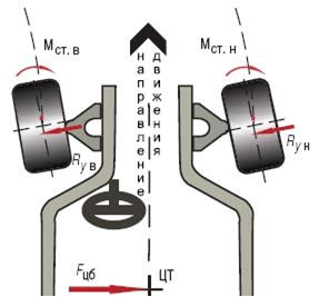 Fig 2
Fig 2
In a turn, side reactions from the action of centrifugal force create moments that return the wheels to a neutral position. (in the presence of a positive caster).
Steering wheel deflection can be caused by the driver's intentional actions associated with a change in direction of travel. In this case, the stabilizing effect assists the driver on corner exit by automatically returning the wheels to neutral. But at the entrance to the turn and in its apex, the "driver", on the contrary, has to overcome the "resistance" of the wheels, applying a certain force to the steering wheel. The reactive force generated on the steering wheel creates what is called steering feel or steering information and to which car designers and automotive journalists pay a lot of attention.
The stabilizing effect occurs due to the presence of a stabilization arm. The stabilization arm is the distance between the point of intersection of the pivot axis and the point of contact of the wheel. This shoulder (and, accordingly, the moment of stabilization) is the greater the greater the angle of inclination of the axis of rotation.
Sometimes the tilt is combined with a slight displacement of the axle in one direction or another from the center of rotation of the wheel. In modern passenger cars, the caster usually takes on positive values that do not exceed ten angular degrees. In this case, the stabilization arm turns out to be small in relation to the dimensions of the wheel. The resulting stabilization moment acting on the wheel consists of two components of the moment from the transverse forces and the moment from the longitudinal forces. Since the transverse shoulder and the side reaction force are much greater than the similar longitudinal ones, the transverse moment also greatly exceeds the longitudinal one. At the moment of action of destabilizing lateral forces in the contact patch of an automobile wheel with the road, sufficiently powerful transverse (lateral) reactions are generated, parrying the disturbance. The point of application of the reaction force of the wheel and its direction depends on the parameters of the tire and is determined by its side slip. Significant deformation of the elastic tire in the radial, tangential and tangential directions is the main reason for the difference between the stabilization mechanism of an automobile wheel and weakly or not at all deformable wheels of pianos and grocery carts. As a result, the character of stabilization changes from "longitudinal" to "transverse".
See Figure 3 for more information on side slip, side reaction mechanism, and stabilizing moment.
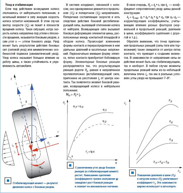
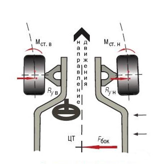
Figure 4 A sudden action of a lateral force, such as a gust of wind, causes the car to move smoothly against the disturbance.
Increasing the pitch angle in positive side in general, has positive consequences, but leads to an increase in steering effort. This means that the load on the amplifier and steering gear parts is increasing. Therefore, the choice of caster is again a compromise, which in modern passenger cars is achieved at values of the order of + 2-6 °. Smaller values are usually typical for machines with a large axle load - so as not to excessively increase the force on the steering wheel. Mercedes-Benz designers are known for their uncharacteristic approach to choosing a caster. For a larger proportion of "Mercedes" the longitudinal angle of inclination of the axis of rotation lies in the range of + 10-12 °. Why is it so?
The fact is that in this way the designers reinforce another favorable consequence of the caster. The longitudinal inclination of the axis of rotation leads to a significant change in the camber of the steered wheels when they turn. The mechanism of dependence is easier to understand if we imagine a hypothetical situation when the axis of rotation of the wheel is horizontal (caster is +90°). In this case, the "turn" of the steered wheel is completely transformed into a change in its inclination relative to the roadway, i.e. collapse. When turning, the camber of the outer wheel becomes more negative, and the inner wheel becomes more positive, this has a beneficial effect on the stability of the car during maneuvers. The larger the caster, the greater the change in camber angles in a turn. Therefore, sometimes (as in the case of M-B), the angle of inclination of the axis of rotation is deliberately increased. In order not to exceed the allowable force on the steering wheel (not to increase the stabilization arm excessively), the axis of rotation is displaced in the longitudinal direction so that it passes at some distance behind the axis of rotation of the wheel.
It turns out that the caster causes a moment of stabilization, the magnitude of which depends, among other things, on the collapse associated with it. Experiments that were bmw car 323i showed that when driving in a straight line, a moment of about 40 N.m acts on each of its steered wheels. From this it becomes clear what a violation of the caster adjustment can lead to. The difference in this parameter for the left and right wheels affects the ability of the car to keep a straight line. If it exceeds 1°, the difference in the moments on the steered wheels becomes noticeable and there is a lateral drift of the car in the direction of the wheel with a smaller caster. This is, in general, negative phenomenon sometimes used for good and intentionally give slightly different values to the caster and camber angles of the steered wheels of different sides. For example, a car designed for right-hand traffic, due to the profiling of the roadway, experiences a drift towards the side of the road. To compensate, the right wheel is set with slightly more negative camber and slightly more positive caster.
Naturally, this procedure can be done only if such an opportunity is provided. Recently, automakers have been trying to relieve servicemen from the worries of adjusting the camber, and even more so the caster. These parameters are increasingly only controlled.
Any UUK control procedure must be preceded by checking the level of the body. Especially carefully the position of the body should be controlled when measuring the caster - this parameter directly depends on the difference in its level in front and behind.
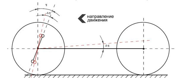
Fig5 Changing the level of the body affects the caster and, as a result, the speed stabilization of the steered wheels.
This is worth remembering for those who like to put spacers under the rear of the body. If appearance a car that takes an indecent pose is only a matter of taste, then a decrease and even a complete loss of high-speed stabilization of the steered wheels is a safety issue, including the safety of innocent "accomplices" traffic. Adjusting the caster does not have a noticeable effect on tire wear.
It is curious that thirty years or more ago in the specifications for cars one could see a diametrically opposite picture - in most cars the caster was negative. The reason is that "light steering" was then in vogue. Since power steering was a novelty, the engineers fought in this way to ensure that the car steered at speed with “one finger”. At the same time, sufficient high-speed stabilization of the wheels was achieved due to the widespread use of diagonal tires. They are more prone to deformation than radial tires. As a result, even with a negative inclination of the axis of rotation, the longitudinal drift of the lateral reaction turned out to be sufficient to create a stabilizing moment. If modern radial tires are installed on such a “retro car”, it will scour from side to side. You can fix the problem by adjusting the caster - you need to give the angle a positive value.
2 Steering Axis Inclination (SAI).
The transverse inclination of the axle has a significant impact on the behavior of the car. Its control is very important in the diagnosis of the suspension. The influence of the transverse angle of inclination is explained by the presence weight stabilization effect.
Stabilization, which is achieved due to the "high-speed" caster, i.e. It only works at high enough speeds. When driving and maneuvering at walking speed, the stabilization effect of the caster is negligible. To force the steered wheels to resist the deviation from the neutral position and automatically return to it after the cessation of the forces that caused the deviation at low speeds, stabilization is used due to the weight of the car falling on the steered wheel. Weight stabilization occurs mainly due to the tilt of the axis of rotation in the transverse direction. Why "mainly"? Because “non-mainly” the caster also contributes to the weight stabilization of the wheels, but here its influence is secondary.
The weight stabilization mechanism works like this. When the wheel turns, its trunnion moves along an arc of a circle, the plane of which is perpendicular to the axis of rotation. If the axis is vertical, the trunnion moves horizontally. If the axis is tilted, the trajectory of the trunnion deviates from the horizontal.

Fig. 6. When the wheel is rotated around an inclined axis, its trunnion, moving in an arc, rises and falls.
The arc described by the trunnion has a vertex and descending sections. The position of the upper point of the arc is determined by the direction of inclination of the axis of rotation of the wheel. With a transverse tilt, the top of the arc corresponds to the neutral position of the wheel. This means that when the wheel deviates from neutral in any direction, the trunnion (and with it the wheel) will tend to fall below the initial level. The wheel works like a jack - it lifts the part of the car above it. The “jack” is counteracted by a force that directly depends on a number of parameters: the weight of the raised part of the car, the angle of inclination of the axle, the magnitude of its lateral displacement and the angle of rotation of the wheel. She tries to return everything to its original, stable position, i.e. turn the steering wheel to neutral. It turns out that due to the transverse inclination of the axis of rotation, the car itself helps the driver to "take off"
Caster also contributes to the weight stabilization of the steering. If the axis of rotation of the wheel is simultaneously tilted in the transverse and longitudinal directions, the arc that the wheel trunnion describes changes orientation. Its top is displaced so that the trunnions of both wheels in the neutral position are on the descending part of the arc. As a result, when the steering wheel is turned, one of them moves in an arc up, the other down. The result is a roll of the front part of the body, an increase in the loading of one of the wheels and an increase in its weight stabilization. This effect is also used to optimize the position of the car body in a turn. The weight stabilization mechanism always works. On a stationary or slow moving car, he acts alone, with increasing speed he is increasingly accompanied by dynamic stabilization.
The choice of the SAI value is the search for the optimum. With a decrease in the transverse angle, the effectiveness of weight stabilization decreases. Excessive lean results in excessive steering force when maneuvering at high angles, such as when parking.
The transverse angle, camber and offset of the wheel determine such important parameter like a running shoulder. This is the distance from the center of the contact patch to the trace of the axis of rotation i.e. points of intersection of the axis of rotation with the ground level.
The longitudinal forces acting on the steered wheels create moments that tend to turn them around the axis of rotation. The shoulder of these moments is equal to the running-in shoulder. In the case of equal forces on both wheels, the moments turn out to be “mirror”, i.e. equal and opposite directions. Mutually compensating each other, they do not affect wheel. However, the moments load the details of the steering trapezium with tensile or compressive (depending on the location of the running shoulder) forces. To limit these loads, the break-in shoulder should not be unnecessarily large. Nevertheless, in most cases, "it can not be."
The break-in shoulder is one of the parameters that affects the steering sensitivity. Thanks to him, the steering wheel "signals" the driver about the violation of the equality of longitudinal reactions on the steered wheels, which may be the result of passing obstacles and road roughness, unequal distribution braking forces between right and left wheel, etc. In these cases, a sudden imbalance of the moments of longitudinal forces is transmitted through the steering wheel to the driver's hands. The main thing is that the "signal" is not excessive and does not reduce the comfort and safety of driving. This important condition is taken into account when designing a car and is often violated (more often unconsciously) during its operation. The fact is that the size of the running-in shoulder is significantly affected by the design of the wheel. The craze for wide wheels with low-profile tires, as well as the installation of wheels with abnormal offset, can cause a critical change in steering sensitivity.
The running arm can be either positive or negative. Typically, a negative running-in arm is used on vehicles with a diagonal dual-circuit brake system. Such a measure allows you to stabilize the behavior of the car in an emergency - in the event of a failure or a decrease in the efficiency of one of the circuits. The imbalance of the braking forces leads to the appearance of a moment that tends to turn the car around the center of mass. With a negative running-in shoulder, at the same time, the inequality of braking forces causes the steered wheels to turn in the direction of reducing the turn of the car. A similar mechanism operates with a sudden increase in longitudinal reaction on one of the steered wheels. For example, when a tire punctures, causing an increase in the rolling resistance force. Thanks to the negative running-in arm, the wheels in this case also turn in such a way that they fend off the spontaneous turn of the car.
The running shoulder is usually chosen within plus 50 minus 20 mm. Some vehicles with independent suspension front wheels in an unloaded state, it can reach 60-80 mm. With a positive run-in shoulder, SAI in most cases is 6-12 °, with a negative one - 11-19. Fig 7,8,9
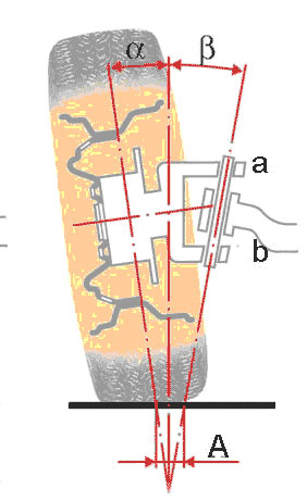
Fig7 α-camber angle, β-transverse angle of the pivot axis, α+β=included angle, A-running arm.
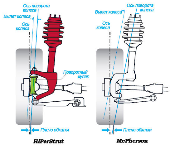
Fig8. The running-in shoulder is positive if it is located on the inner part of the tread relative to the wheel axis and negative if it is on the outer.
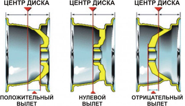
Fig9 Installing a wheel with a non-standard offset changes the break-in shoulder
The transverse inclination of the axis of rotation of the steered wheels, as we found out, affects the stabilization and steering sensitivity. Therefore, SAIs are especially carefully checked when there are problems with these vehicle characteristics. Lateral lean angle is also recommended to be controlled in the event of vehicle side drift that cannot be corrected by adjusting the caster and camber. Its cause may be a noticeable (more than 1 °) difference in the SAI of the right and left wheels. When controlling SAI, it must be borne in mind that this parameter depends on the camber angle of the wheel (with a decrease in camber, SAI increases and vice versa), so its check must be preceded by a camber correction. SAI deviation from the norm indicates a shift in the coordinates of one or both suspension points that set the position of the axis of rotation. The cause of the displacement may be, for example, deformation of the pivot pin, shock absorber mounting cup, arm, front subframe or incorrect adjustment of the latter, if any.
The choice of CCA is a complex problem aimed at finding the optimum and solved by the method of successive approximations. The solution starts with a kinematic calculation of the position of the wheels for various driving conditions. Determining the behavior of a wheel in suspensions of a relatively simple design (double-lever or MacPherson strut) does not cause difficulties. The calculation of multi-link suspensions is performed using computer simulation methods. Next, they analyze how changing the orientation of the wheel affects the contact patch and what consequences this will have on the critical characteristics of the car: stability, handling, tire wear rate, etc. By varying the kinematics of the suspension, "on paper" they achieve an acceptable result, which becomes the starting point for the most important stage - experimental fine-tuning.
During the tests, a large number of special tests are performed (movement in a straight line, in a circle, in a turn, with a “rearrangement”, etc.), objective indicators are recorded (angle of rotation and force on the steering wheel, top speed maneuver without breaking off the wheel, the temperature of different tread zones, etc.) and the subjective feelings of the test pilots. Often, experiments completely cross out the theory and bring results that are paradoxical from a theoretical point of view. This suggests that the optimal UUK complex is a kind of harmony that cannot be "verified by algebra".
It is worth emphasizing that as a result of wheel slip under the action of a lateral force (force slip), the resultant of elementary lateral reactions always turns out to be shifted back in the direction of movement from the center of the contact area. That is, the stabilizing moment acts on the wheel even when the trace of the axis of rotation coincides with the center of the contact patch. The question arises: why do you need a caster at all? The fact is that the stabilizing moment (Mst) depends on various factors (tire design and pressure in it, wheel load, road grip, longitudinal forces, etc.) and is not always sufficient for optimal stabilization of the steered wheels. In this case, the stabilization arm is increased by the longitudinal inclination of the axis of rotation, i.e. positive caster. The destabilizing forces acting on the wheel of a moving car depend on the speed and mass. Accordingly, both lateral reactions and stabilizing moments increase with increasing speed. Therefore, the stabilization of the steered wheels, to which the caster makes a significant contribution, is called high-speed. At low speeds, the influence of this mechanism becomes insignificant. Looking ahead, we mention that weight stabilization works here, for which the tilt of the axis of rotation of the wheel in the transverse direction is responsible.
Setting the axis of rotation of the steering wheels with positive caster is useful not only for their stabilization. A positive caster eliminates the danger of a sudden change in trajectory and even a rollover of the car under the influence of a sudden lateral force. It may be due to a gust of wind or movement across the slope. Thanks to the positive caster, the car smoothly turns “downwind” or “downhill” even with the steering wheel released.
On almost all sports cars, the front wheels are set with negative camber, the only question is how much to set this camber. Often high speed cars run with more negative camber because it is supposed to help improve handling, especially when cornering. The negative camber provided by the front suspension improves the position of one wheel relative to the road. It could be the left front wheel in a right turn or the right wheel in a left turn. This wheel has a high dynamic load, so it is important to set the camber correctly to ensure the correct position of the wheel relative to the road.
So, the correct installation of a heavily loaded front wheel is a very important task. Let's take an extreme case (unfortunately, found on some early generation cars) as a basic idea for installing a wheel. We will consider the behavior of the right front wheel in a left turn. The suspension geometry provides a positive camber of the front wheels up to 5÷7 degrees. When cornering at high speed, the tires look like they want to come off the rim and the car is clearly not handling well. Suffice it to say that some changes in the geometry of the suspension (increasing the longitudinal inclination of the steering axis to provide dynamic negative camber, increasing the static negative camber, installing more rigid springs suspensions to reduce body roll, lowering the height of the suspension, changing the position of the suspension arms, etc. etc.) will lead to a completely different behavior of the same car moving at the same speed in the same turn. The car can be made fully manageable, especially in comparison with the original version.
Many sports cars with large negative camber (up to 2.5÷3.5 degrees) do not always have good performance handling and have very fast wear on the inner edge of the tire. Often such machines exhibit understeer. The reason lies in the fact that with too large a camber angle of the front wheels, the contact patch of the tire with the road of the loaded wheel decreases the more, the more the wheel is turned. This effect is more pronounced on light vehicles with very wide tires.
Consider the behavior of the car under heavy braking. The front of the car "dives" and in the suspension there is almost always an additional negative camber. So, when braking, you need to have the maximum contact patch of the tire with the road. To ensure maximum braking efficiency, the wheels should be located as close to the vertical as possible, without any camber and convergence (in practice, this can never be realized).
It is believed that the most acceptable static negative camber should be within 0.5÷1.5 degrees. Negative camber settings greater than 1.5 degrees should be avoided.
Pitch (Castor)
The longitudinal inclination of the axis of rotation of the wheel is defined as the angle between the vertical, restored from the point of contact of the wheel with the road, and the line connecting the centers of the ball joints of the steering knuckle (wheel hub). The longitudinal inclination of the axis of rotation leads to a change in the camber when the wheel is turned to the left and to the right from the position of rectilinear movement.
For example, when turning left, the right front wheel gains additional negative camber while the left wheel loses negative camber (moving towards positive camber). Both front wheels must have the same static steering angle. The greater the longitudinal inclination of the axis of rotation, the more the camber will change when turning.
To improve the position of the wheels relative to the road when cornering, the angle of the longitudinal inclination of the axis of rotation can be changed. If the car has a large static negative camber (greater than 2÷3 degrees), it is impossible to change the longitudinal inclination of the steering axis so as to further increase the negative camber in the turn (as you remember, we are talking only about the right front wheel in the left turn). The opposite wheel will lose negative camber anyway, but very rarely zero and almost never positive camber. Basically, the inside (in relation to the turn) wheel does not change the camber as desired. Large static negative camber is usually installed where it is difficult to increase the caster axis to provide sufficient dynamic camber for hard cornering.
When a negative camber angle is set too high on a car for cornering, the outer edge of the tire rarely undergoes noticeable wear, while the inner edge wears significantly. The tire wears out very quickly and is almost always uneven on the inner edge of both wheels.
Suspension adjustments that increase dynamic negative camber can cause understeer in tight corners (understeer is less pronounced in long, gentle corners). It is necessary to do tuning work (of course, on each car differently) in the field of adjusting the characteristics of the suspension, which will ensure the best handling of the car.
It is believed that the most advantageous range of the longitudinal inclination of the axis of rotation is 3÷8 degrees. The initial installation angle of the longitudinal inclination should be equal to 3÷4 degrees, but it should be possible to adjust it in steps of 1 degree to the maximum (8 degrees) value. The caster angle is increased if positive camber of the outer (with respect to the turn) wheel occurs during hard cornering. For low speed vehicles, the pitch angle should be within the range of 2÷7 degrees.
Roll axis tilt (KPI)
|
|
|
|
|
1 - positive offset (attachment plane (C) is between the outer side of the wheel and its symmetry plane (D)), |
|
|
|
|
|
|
|
|
|
|


Modern cars do not have a real kingpin around which the steerable wheel turns. However, the principle of the kingpin in the suspension still remains. The transverse inclination of the pivot axis (pivot) is represented by a line connecting the centers of the ball joints. The roll angle is defined between this line and the axis perpendicular to the axis of rotation of the wheel.
A line passing through the centers of the hub hinges intersects with the road surface at some point, more or less distant from the center of the contact patch. This distance (run-in shoulder) is a rather important indicator.
Usually the intersection point lies inside the contact patch and the rims have a large positive offset. When changing the wheel track using spacers or using a specially designed disc, the situation changes in the direction of deterioration.
Note: wheel offset is the distance between the plane of symmetry of the wheel and the plane of its attachment. Distinguish between positive and negative offset. Departure is considered positive if the mounting plane is between the outer side of the wheel and the plane of its symmetry. With a negative offset, the attachment plane is located between the plane of symmetry of the wheel and its inner side. The term “offset” means the presence of a negative overhang, and “in-set” means the presence of a positive overhang, but in our country it is customary to call both positive and negative overhang the term “offset”, which confuses the terminology. Further in the text, we will indicate which one - positive or negative departure is meant.
The optimal angle of the transverse inclination of the axis of rotation lies in the range of 9÷12 degrees, it is preferable to set it equal to 10 degrees. It is usually not possible to change the roll angle, although its effective value can be changed (within certain limits) by setting the appropriate negative camber.
In the mass production of cars, the wheels are installed with immersion inside the body (positive offset). At the same time, they are guided by the main principle of creating a running-in shoulder: the point of intersection of the axis of rotation of the wheel must be inside the contact patch of the wheel with the road and inside the wheel track. When building sports cars, they sometimes install wheels with a long negative offset just on the basis that "it looks better", often without thinking about the harm done to handling.
Having a wide wheel track is good up to certain limits and, of course, not at the expense of suspension geometry.
We install discs with such a negative offset (or spacers of the appropriate thickness) so that the wheel moves away from the hub by 75 mm, thereby increasing the front wheel track by 150 mm. In connection with the innovations, the steering will show a tendency to multiple reverse impacts, especially on uneven surfaces. This situation is not very good and can result in loss of control of the car. This happens when the wheel hits a ledge. pavement and tends to turn in the direction of the resistance (left wheel wants to turn left, right wheel wants to turn right). This leads to the occurrence of a tilting moment relative to the position of the wheels and their axis of rotation.
The closer the point of intersection of the transverse axis of rotation is located relative to the center of the contact patch (decrease in the running shoulder), the less the effect of the harmful overturning moment and vice versa.
Let's consider another case. Let the wheel with a large negative offset run into an uneven surface (for example, the left one). The other wheel (right) remains on a level surface. The car then tends to turn left.
Sometimes a kart-like suspension geometry is used (with a very large negative offset). This leads to the fact that when the wheel is turned from the straight-line position, one side of the chassis rises, and the other falls. So, if the car turns left, the left front wheel tends to raise the left side of the body, the right wheel tends to lower this side of the car. The more negative the overhang, the more pronounced this trend (forced change in body geometry).
Many vehicles are equipped with wheels with a large negative offset, but only those cases in which this is harmful should be considered. If you want to increase the track of the car, then you should make new suspension and steering arms than install spacers to increase the negative offset or wheel disks with increased negative reach. This is of course time consuming but also the most effective way to get a well-controlled car.
In accordance with the above, the point of intersection of the axis of rotation of the wheel with the surface, at least should be located on the inner edge of the tire, however, the car's handling is better when this point lies in the center of the contact patch.
Avoid installing wheels with too much negative offset. Note that modern sports cars have wheels with a large positive offset.
The relationship between pitch and roll angles
These two geometric factors are closely related, because at a given steering angle, the front wheels change their camber when any of these factors changes. For example, if the car turns to the right, the left front wheel acquires additional negative camber, while the right wheel loses negative camber, sometimes up to positive. In the opposite turn, the change in camber angles changes direction. The behavior of the suspension can be monitored in stationary conditions: let someone turn the steering wheel, and you watch the change in the position of the wheels relative to the floor.
The combination of pitch and roll angles can lead to the desired dynamic camber pattern. For example, if the hub has 9 degrees of lateral tilt at 6 degrees of caster, camber increases more for a given steering angle than with a combination of 12 degrees of lateral and 3 degrees of caster. However, it is easier to adjust the longitudinal slope than the transverse one.
The desired law of camber change for a given angle of lateral inclination of the axis of rotation can be obtained by adjusting only the longitudinal inclination. Once you understand the basic principle of suspension operation, your view of front suspension geometry will never remain constant: the more knowledge and experience you gain, the more interesting it will be to change the suspension settings. Chapter 2. Suspension height Chapter 10. Vehicle testing and adjustments