Indication is understood as the removal with subsequent processing of indicator diagrams, which are a graphical dependence of the pressure developed in the working cylinder as a function of the piston stroke S or the volume of the cylinder proportional to it V s (see Fig. 1 and 2).
Indicators "Maygak"
Diagrams are taken from each working cylinder using a special device - the Maygak piston-type indicator. The presence of a diagram allows you to determine the parameters important for the analysis of the workflow P i , P c and P max. The diagram in fig. 1 is typical for engines, during the operation of which the main task was to reduce the level and content of nitrogen oxides in the exhaust. For this, as already noted, a later fuel injection is carried out and combustion occurs with a smaller increase in pressure and temperatures in the combustion chamber.
Rice. 1 Indicator diagram of the MAN-BV KL-MC engine
If the main goal is to increase the efficiency of the engine, then combustion is organized with an earlier fuel supply and, accordingly, a large increase in pressure. In the presence of electronic system fuel supply control, such a restructuring is easily carried out.
On the diagram in fig. 2, two humps are clearly visible - compression and then combustion. This character is achieved due to an even later fuel supply. The figures show two types of diagrams - a collapsed one, which determines the average indicator pressure, and an expanded one, which allows you to visually assess the nature of the development of processes. Similar diagrams can be obtained using the Maygak piston indicator, which requires the presence of a
 Rice. 2 MAN-BV SMC engine indicator diagram
 synchronize the rotation of the indicator drum with the movement of the piston of the indicated cylinder. Connecting the drive allows you to get a collapsed diagram, the planimetric area of which is determined mean indicator pressure, which is a certain average conditional pressure acting on the piston and performing work during one stroke equal to the work of gases per cycle.
P i = F ind.d / L m, where F ind.d- the area of the diagram, proportional to the work of gases per cycle, L- the length of the diagram, proportional to the size of the working volume of the cylinder, m is a scaling factor that depends on the stiffness of the indicator piston spring.
By Pi counted cylinder indicator power N i = C P i n, where η - number of revolutions 1/min and FROM is the constant of the cylinder. Effective power N e = N i η fur kW, η fur-mechanical engine efficiency, which can be found in the engine documentation.
Before proceeding with the indication, check the condition of the indicator cock and drive. Possible errors in their state are illustrated in fig. 3.
The comb (Fig. 2) is removed by manually operating the cord, disconnected from the indicator drive. The presence of a comb allows you to evaluate the stability of cycles and more accurately measure R max. If the peaks are the same, then this indicates stable operation of the fuel equipment.
It is important to note that piston indicators have a low frequency of natural oscillations. The latter must be at least 30 times the engine speed. Otherwise, the indicator charts will be distorted. Therefore, the application
 Rice. 3 Errors in setting the indicator drive
 piston indicators are limited to 300 rpm. Rod spring indicators have a higher frequency of natural oscillations and their use is allowed in engines with a speed of up to 500-700 rpm. However, in such engines there is no indicator drive and one has to limit oneself to removing combs or expanded diagrams, from which the average cannot be determined.
The second limitation concerns the value maximum pressure in cylinders. IN modern engines with a high level of forcing, it reaches 15-18 MPa. With the piston used in the "Maygak" indicator for diesel engines with a diameter of 9.06 mm, the most rigid spring limits P max \u003d 15 MPa. With such a spring, the measurement accuracy is very low, since the scale of the spring is 0.3 mm per 0.1 MPa.
It is also significant that the work of indexing is rather tedious and time-consuming, and the accuracy of the results is low. The low accuracy is due to errors arising from the imperfection of the indicator drive and inaccuracy in the processing of indicator diagrams during their manual planning. For information- the inaccuracy of the indicator drive, expressed in the displacement of the TDC of the drive from its true position by 1 °, leads to an error of about 10%.
The main difference between a 2-stroke engine and a 4-stroke one is the method of gas exchange - cleaning the cylinder from combustion products and charging it with fresh air or a hot mixture.
Gas distribution devices of 2-stroke engines - slots in the cylinder liner, blocked by a piston, and valves or spools.
Duty Cycle:
After the combustion of the fuel, the process of expansion of gases (working stroke) begins. The piston moves to bottom dead center (BDC). At the end of the expansion process, piston 1 opens inlet slots (windows) 3 (point b) or exhaust valves open, communicating the cylinder cavity through exhaust pipe with atmosphere. In this case, part of the combustion products leaves the cylinder and the pressure in it drops to the purge air pressure Pd. At point d, the piston opens purge windows 2, through which a mixture of fuel and air is supplied to the cylinder at a pressure of 1.23-1.42 bar. Further fall slows down, because. air enters the cylinder. From point d to BDC, outlet and purge windows are simultaneously open. The period during which the purge and exhaust ports are open at the same time is called purge. During this period, the cylinder is filled with a mixture of air, and the combustion products are displaced from it.
The second stroke corresponds to the piston stroke from bottom to top dead center. At the beginning of the stroke, the purge process continues. Point f - the end of the purge - the closing of the inlet windows. At point a, the outlet windows close and the compression process begins. The pressure in the cylinder at the end of charging is slightly higher than atmospheric pressure. It depends on the purge air pressure. From the moment the purge is completed and the exhaust windows are completely closed, the compression process begins. When the piston does not reach 10-30 degrees along the angle of rotation of the crankshaft to TDC (point c /), fuel is supplied to the cylinder through the nozzle or the mixture is ignited and the cycle is repeated.
With the same cylinder dimensions and rotational speed, the power of the 2-stroke is much greater, 1.5-1.7 times.
Average pressure of the theoretical ICE diagram.

The average indicator pressure of the internal combustion engine.
 This is such a conditionally constant pressure, which, acting on the piston, does work equal to inner work gas throughout the entire working cycle.
Graphically, p i on a certain scale is equal to the height of the rectangle mm / hh / , equal in area to the area of the diagram and having the same length.
f- area of the indicator diagram (mm 2)
l- length of index diagram - mh
k p - pressure scale (Pa/mm)
Average effective pressure of internal combustion engine.
This is the product of the mechanical efficiency and the average indicator pressure.
Where η mech =N e /N i . During normal operation η mech =0.7-0.85.
Mechanical efficiency of the internal combustion engine.
η fur \u003d N e / N i
Ratio of effective power to indicator power.
During normal operation η mech =0.7-0.85.
The indicator power of the internal combustion engine.
Ind. the engine power received inside the wheeled wheel can be determined using an indicator diagram taken by a special device - an indicator.
Ind.power - the work done by the working fluid in the engine cylinder in a unit of time.
Individual power of one cylinder -
k- engine power
V-cylinder displacement
n is the number of working moves.
The effective power of the internal combustion engine.
Useful power taken from the crankshaft
N e \u003d N i -N tr
N tr - the sum of power losses due to friction between moving parts of the engine and to actuate auxiliary mechanisms (pumps, generator, fan, etc.)
Determination of the effective power of the engine in laboratory conditions or during bench tests is carried out using special braking devices - mechanical, hydraulic or electrical.
30.09.2014
Operating cycle - a set of thermal, chemical and gas-dynamic processes, successively, periodically repeating in the engine cylinder in order to convert the thermal energy of the fuel into mechanical energy. The cycle includes five processes: intake, compression, combustion (combustion), expansion, release.
Diesel and carburetor four-stroke engines are installed on tractors and vehicles used in the timber industry and forestry. Forestry vehicles are mainly equipped with four-stroke diesel engines,
During the intake process, the engine cylinder is filled with a fresh charge, which is purified air for a diesel engine or a combustible mixture of purified air with fuel (gas) for diesel engines. carburetor engine and gas diesel. A combustible mixture of air with finely dispersed fuel, its vapors or combustible gases must ensure the spread of the flame front in the entire occupied space.
During the compression process, the working mixture is compressed in the cylinder, consisting of a fresh charge and residual gases (carburetor and gas engines) or from fresh charge, atomized fuel and residual gases (diesels, multi-fuel and gasoline injection engines and gas diesels).
Residual gases are called combustion products remaining after the completion of the previous cycle and participating in the next cycle.
In engines with external mixture formation, the operating cycle proceeds in four cycles: intake, compression, expansion and exhaust. Intake stroke (Fig. 4.2a). Piston 1, driven by rotation crankshaft 9 and connecting rod 5, moving to BDC, creates a vacuum in cylinder 2, as a result of which a fresh charge of the combustible mixture enters through pipeline 3 through inlet valve 4 into cylinder 2.
The compression stroke (Fig. 4.2b). After filling the cylinder with a fresh charge, the intake valve closes, and the piston, moving to TDC, compresses the working mixture. This increases the temperature and pressure in the cylinder. At the end of the cycle, the working mixture is ignited by a spark that occurs between the electrodes of spark plug 5, and the combustion process begins.
Extension stroke or power stroke (fig. 4.2e). As a result of the combustion of the working mixture, gases (combustion products) are formed, the temperature and pressure of which increase sharply by the time the piston reaches TDC. Under the influence of high gas pressure, the piston moves to the BDC, while doing useful work transmitted to the rotating crankshaft.
Release stroke (see Fig. 4.2d). In this stroke, the cylinder is cleaned of combustion products. The piston, moving to TDC, through the open exhaust valve 6 and pipeline 7 pushes the combustion products into the atmosphere. At the end of the stroke, the pressure in the cylinder slightly exceeds atmospheric pressure, so some of the combustion products remain in the cylinder, which mix with combustible mixture filling the cylinder during the intake stroke of the next working cycle.
The fundamental difference between the operating cycle of an engine with internal mixture formation (diesel, gas-diesel, multi-fuel) is that on the compression stroke, the fuel supply equipment of the engine power system injects finely atomized liquid motor fuel, which is mixed with air (or a mixture of air with gas) and ignites. The high compression ratio of a compression ignition engine allows the mixture in the cylinder to be heated above the autoignition temperature of the liquid fuel.
The working cycle of a two-stroke carburetor engine (Fig. 4.3) used to start a skidder diesel is completed in two piston strokes or in one revolution of the crankshaft. In this case, one cycle is working, and the second is auxiliary. In a two-stroke carburetor engine, there are no intake and exhaust valves, their function is performed by intake, exhaust and purge windows, which open and close with the piston as it moves. Through these windows, the working cavity of the cylinder communicates with the inlet and outlet pipelines, as well as with the sealed crankcase of the engine.

Indicator diagram. Operating or actual engine cycle internal combustion differs from the theoretical one studied in thermodynamics by the properties of the working fluid, which is real gases of variable chemical composition, the rate of heat supply and removal, the nature of the heat exchange between the working fluid and the parts surrounding it, and other factors.
Actual engine cycles are graphically depicted in the coordinates: pressure - volume (p, V) or in coordinates: pressure - crankshaft rotation angle (p, φ). Such graphical dependences on the specified parameters are called indicator diagrams.
The most reliable indicator diagrams are obtained experimentally, instrumental methods, directly on the engines. The indicator diagrams obtained by calculation on the basis of thermal calculation data differ from the actual cycles due to the imperfection of the calculation methods and the assumptions used.
On fig. 4.4 shows indicator diagrams for four-stroke carburetor and diesel engines.
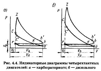
The circuit r, a, c, z, b, r is a diagram of the operating cycle of a four-stroke engine. It reflects five alternating and partially overlapping processes: intake, compression, combustion, expansion and exhaust. The intake process (r, a) starts before the piston arrives at BMT (near point r) and ends after HMT (at point k). The compression process ends at point c, at the moment of ignition of the working mixture in a carburetor engine or at the moment fuel injection begins in a diesel engine. At point c, the combustion process begins, which ends after point r. The expansion process or work stroke (r, b) ends at point b. The release process begins at point b, i.e. at the moment the exhaust valve opens, and ends after point r.
The area r, a, c, b, r is built in p-V coordinates, therefore, on a certain scale it characterizes the work developed by the gases in the cylinder. The indicator diagram of a four-stroke engine consists of positive and negative areas. The positive area is limited by the lines of compression and expansion k, c, z, b, k and characterizes the useful work of gases; the negative one is limited by the intake and exhaust lines and characterizes the work of gases expended to overcome the resistance during intake and exhaust. The negative area of the diagram is insignificant, its value can be neglected, and the calculation is made only along the contour of the diagram. The area of this contour is equivalent to the indicator work, it is planned to determine the average indicator pressure.
The indicator work of the cycle is called the work in one cycle, determined by the indicator diagram.
The average indicator pressure is such a conditional constant pressure in the engine cylinder at which the work of the gas in one piston stroke is equal to the indicator work of the cycle.
The average indicator pressure p is determined from the indicator diagram:
Average effective Re pressure is the pressure that depends on the amount of fuel injected into the cylinder.
Effective power Re- power taken from the connecting flange of the motor shaft, i.e., given to the shafting, generator or any consumer of energy in this mode of operation
Indicator power Pz- the power developed by gases inside the working cylinders of the engine is called indicator power.
3. Basic electrical quantities - electric current, voltage, power
electric current, units of measurement.
ELECTRICITY- ORDERED UNCOMPENSATED MOTION OF FREE ELECTRICLY CHARGED PARTICLES UNDER THE INFLUENCE OF ELECTRIC FIELD.
VOLTAGE - THE AMOUNT OF ENERGY EXPECTED TO MOVEMENT FROM ONE POINT TO ANOTHER.
ELECTRIC CURRENT POWER– RATE OF ENERGY CHANGE. THE POWER OF ELECTRIC CURRENT IS EQUAL TO THE WORK OF ELECTRIC CURRENT PRODUCED FOR ONE SECOND.
4. General requirements for the maintenance of STS and K.
SHIP'S EQUIPMENT IS MEAN INSTALLATIONS, UNITS, MECHANISMS AND OTHER EQUIPMENT OF THE SHIP THAT ENSURE ITS PERFORMANCE IN ACCORDANCE WITH THE PURPOSE.
1. General Provisions 1.1. Technical operation of ships technical means and structures (STS and K) must be carried out in accordance with the instructions of manufacturers and the requirements of these Rules.
1.2. All operations related to commissioning, changing operating modes, decommissioning, cranking and disassembly of technical equipment must be carried out with the permission, at the direction or with the notification of officials (master, watch officer, chief engineer, watch engineer responsible for the management ), if it is provided for by the relevant paragraphs of the Rules or other documents regulating the actions of the ship's crew. 1.3. Omissions related to the technical use, maintenance and repair of STSiK should be recorded by the watch mechanic in the engine log. 1.4. On the ship, accounting of the technical condition of STSiK should be organized, as well as accounting for the availability and movement of spare parts and items, material and technical supply according to departments.
1.5. When the equipment is in operation in the water, make sure that the equipment is in good condition, the instrumentation is in good order and so on.
TICKET 2.
1. Landing and stability of the vessel, theoretical foundations. Stability, metacentric height. Stability information.
STABILITY- the ability of a floating facility to withstand external forces that cause it to roll or trim and return to a state of equilibrium.
The ship floats on the surface of the water under the influence of two main forces: gravity and Archimedean force. The force of gravity - “pulls the ship down”, is equal to its weight and is applied to the center of gravity of the CG ship. The buoyancy force or Archimedean force - “pushes the vessel out of the water”, is equal to its displacement and is applied in the center of the underwater volume of the vessel's CV.
In the "straight" position of the ship, these forces balance each other and lie on the same vertical line. With a roll, the shape of the underwater part of the hull will change, the CV will shift towards the heeled side, and a so-called restoring moment will arise, which counteracts the roll. When the ship is tilted, the CV rotates around a point called the metacenter m.
The distance from the metacenter m to the center of gravity of the CG (metacentric height) is a characteristic of the ship's stability. The smaller the vessel, the greater the metacentric height should be. The lower the center of gravity, the more stable the ship. There is a simple rule: EVERY KILOGRAM UNDER THE WATERLINE INCREASES STABILITY, AND EVERY KILOGRAM ABOVE THE WATERLINE WORKS IT.
SCHEME OF OPERATION OF A 4-STROKE DIESEL.
ICE MARKING.
Domestic diesel engines are marked in accordance with GOST 4393-74. Each type of engine has a conventional letter and number designation:
H - four-stroke
D - two-stroke
DD - two-stroke double action
R - reversible
C - with reverse clutch
P - s reduction gear
K - crosshead
H - supercharged
G - for operation on gas fuel
GZh - for operation on gas-liquid fuel
The numbers in front of the letters indicate the number of cylinders; the numbers after the letters are the cylinder bore/stroke in centimeters. For example: 8DKRN 74/160, 6ChSP 18/22, 6Ch 12/14
Marking of foreign diesel companies:
Engines of the SKL plant in Germany (former GDR)
Four-stroke internal combustion engines are called engines in which one stroke (stroke) is carried out in four piston strokes, or two revolutions of the crankshaft. The strokes are: intake (filling), compression, stroke (expansion), exhaust (exhaust).
I measure - FILLING. The piston moves from TDC to BDC, as a result of which a vacuum is created in the over-piston cavity of the cylinder, and air from the atmosphere enters the cylinder through the open intake (suction) valve. The volume in the cylinder is constantly increasing. The valve closes at BDC. At the end of the filling process, the air in the cylinder has the following parameters: pressure Pa=0.85-0.95 kg/cm 2 (86-96 kPa); temperature Ta=37-57°C (310-330 K).
II measure - COMPRESSION. The piston moves in the opposite direction and compresses a fresh charge of air. The volume in the cylinder decreases. Pressure and temperature rise to the following values: Pc=30-45kg/cm 2 (3-4 MPa); Tc = 600-700°C (800-900 K). These parameters must be such that self-ignition of the fuel occurs.
At the end of the compression process, finely atomized fuel is injected into the engine cylinder from a nozzle under a high pressure of 20-150 MPa (200-1200 kg / cm 2), which spontaneously ignites under the action of high temperature and burns out quickly. Thus, during the second cycle, air is compressed, fuel is prepared for combustion, the working mixture is formed and its combustion begins. As a result of the combustion process, the gas parameters increase to the following values: Pz=55-80kg/cm 2 (6-8.1 MPa); Tz=1500-2000°C (1700-2200 K).
III beat - EXPANSION. Under the action of forces arising from the pressure of the products of combustion of the fuel, the piston moves to the BDC. The thermal energy of gases is converted into mechanical work of moving the piston. At the end of the expansion stroke, the gas parameters are reduced to the following values: Pb=3.0-5.0 kg/cm 2 (0.35-0.5 MPa); Tb=750-900°C (850-1100 K).
IV measure - RELEASE. At the end of the expansion stroke (up to BDC), the exhaust valve opens and gases with energy and pressure greater than atmospheric rush into an exhaust manifold, moreover, when the piston moves to TDC, the exhaust gases are forced to be removed by the piston. At the end of the exhaust cycle, the parameters in the cylinder will be as follows: pressure P 1 =1.1-1.2 kg/cm 2 (110-120 kPa); temperature T 1 =700-800°C (800-1000 K). After TDC, the exhaust valve closes. The work cycle is over.
Depending on the position of the piston, the change in pressure in the engine cylinder can be depicted graphically in the coordinate axes PV (pressure - volume) of a closed curve, which is called an indicator diagram. In the diagram, each line corresponds to a specific process (cycle):
1-a - filling process;
a-c - compression process;
c-z" - combustion process at constant volume (V=const);
z"-z - combustion process at constant pressure (P=const);
z-b - expansion process (work stroke);
b-1 - release process;
Po - atmospheric pressure line.
Note: if the diagram is located above the Po line, then the engine is equipped with a pressurization system and has a large power.
The extreme positions of the piston (TDC and BDC) are shown by dotted lines.
The volumes occupied by the working fluid, in any position of the piston and enclosed between its bottom and the cylinder cover, are plotted on the abscissa axis of the diagram, which have the following designations:
Vc is the volume of the compression chamber; Vs is the working volume of the cylinder;
Va. is the total volume of the cylinder; Vx is the volume above the piston at any moment of its movement. Knowing the position of the piston, you can always determine the volume of the cylinder above it.
On the y-axis (in the selected scale) lay the pressure in the cylinder.
Considered indicator diagram shows the theoretical (calculated) cycle where assumptions are made, i.e. strokes begin and end at dead points, the piston is at TDC, the combustion chamber is filled with residual exhaust gases.
IN real engines the moments of opening and closing of the valves do not begin and end at the dead points of the piston position, but with a certain offset, which is clearly seen in the circular valve timing diagram. The moments of opening and closing of valves, expressed in degrees of rotation of the crankshaft (p.k.v.) are called valve timing. The optimal opening and closing angles of the valves, as well as the start of the fuel supply, are determined experimentally when testing a prototype at the manufacturer's stand. All angles (phases) are indicated in the motor log.
By the time the air charge enters the engine cylinder, the suction valve opens. Point 1 corresponds to the position of the crank when the valve opens. For better filling of the cylinder with air, the intake valve opens up to TDC and closes after the BDC piston passes through an angle equal to 20-40 ° c.c.v., which is designated as the lead and lag angle of the intake valve. Usually the angle p.k.v. corresponds to an intake process of 220-240°. When the valve closes, the filling of the cylinder ends and the crank takes the position corresponding to point (2).
After the compression process, self-ignition of the fuel takes time for it to heat up and evaporate. This period of time is called the ignition delay period. Therefore, fuel injection is carried out with some advance until the piston reaches TDC at an angle of 10-35 ° c.c.v.
FUEL ADVANCE ANGLE
The angle between the direction of the crank and the axis of the cylinder at the time of the start of fuel injection is called the fuel advance angle. UOPT is counted from the start of supply to TDC and depends on the supply system, fuel grade and engine speed. UOPT in diesel engines is from 15 to 32 ° and is of great importance for the operation of the internal combustion engine. It is very important to determine the optimal feed advance angle, which must correspond to the manufacturer's value specified in the engine passport.
Optimal SPTA is of great importance for normal operation engine and its economy. With proper regulation, fuel combustion should begin before the piston reaches TDC by 3-6 ° p.c.v. Maximum pressure Pz, equal to the calculated one, is achieved when the piston passes the TDC at an angle of 2-3 ° c.c.v. (see "Combustion phases").
With an increase in UOPT, the self-ignition delay period (I-th phase) increases and the bulk of the fuel burns out at the moment the piston goes to TDC. This leads to a hard operation of the diesel engine, as well as to increased wear of the parts of the CPG and the crankshaft.
A decrease in the UOPT leads to the fact that the main part of the fuel enters the cylinder when the piston passes the TDC and burns in a larger volume of the combustion chamber. This reduces the cylinder power of the engine.
After the expansion process, in order to reduce the cost of expelling exhaust gases by the piston, the exhaust valve is opened ahead of time until the piston arrives at BDC by an angle equal to 18-45 ° p.c.v., which is called the exhaust valve opening advance angle. Dot (). For better cleaning of the cylinders from combustion products, the exhaust valve closes after the TDC piston passes to a retard angle equal to 12-20 ° c.c.v., corresponding to the point () on the pie chart.
However, it can be seen from the diagram that the suction and exhaust valves are simultaneously in the open position for some time. This opening of the valves is called the angle of overlap of the phases of the valves, which amounts to a total of 25-55 ° c.c.v.