Many Internet users in Yandex or Google enter a similar request - “repair of the UAZ 469 front axle”. This means that they are interested in how to repair the front or rear axle on the Oise themselves. Of course, the procedure for disassembling and repairing the bridge is described in special books on repair and operation, which are not a problem to get now. However, to disassemble with your own hands what is the front, what is the rear axle to the last screw is, to put it mildly, not an easy task. It may turn out that you just need to replace some small part, to access which you do not have to disassemble everything.
Front axle UAZ 469
Here are just some of the possible options for breakdowns of bridges on the UAZ 469 (Hunter, Patriot, "loaf"):
- Worn differential, bent gearbox housing
- Critical wear of the main gear in the gearbox
- Wear of the steering knuckle (ball joint, trunnion) on the front axle
- The appearance of large gaps in the pivot joints
- Bearing wear resulting in the need for adjustment/replacement
- Injection of elements requiring lubrication
It can be difficult to understand which of the above happened to your car, however, it is often possible even by ear to approximately localize the problem. If increased noise is heard from the side of the front or rear axle, hum (even in neutral gear) - the gearbox is most likely worn out (repair is required), or the bearings require lubrication. If your car “scours” from side to side and at the same time the steering is in order, the problem may sit in the trunnion, CV joint or in the incorrect installation of the pivots that fix the ball joint, as a result of which there is play and the wheel starts to “walk”.
 What is the SHRUS made of?
 A very common malfunction is the departure of ball bearings that are in the CV joint. They fly out just because of the incorrect adjustment of the pivots, as a result of which the geometric center of the CV joint and the trunnion do not match. As a result, the axle shaft "walks" in the seat and gradually breaks. The joint itself is also damaged. And when turning from the side of the wheel, a crunch is heard and at the same time the wheel can wedge. Some masters in the process of repair simply throw out all the balls, except for the centering one (additionally welding it) - in order to get rid of the problem of their constant flying out.
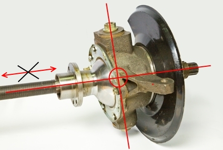 Swivel fist of the front axle UAZ 469 assy
 But this does not save for long, there are even cases when the welded ball breaks off during the ride, the loads are so high there. It is much more effective to do the adjustment of the pivots. It is necessary to achieve such a state in which the line passing through the pivots and the center of the axle shaft will intersect at one point. And it is at this point that the center of the CV joint should be located. The displacement of the axle shaft to the left and right, as shown in the figure, is unacceptable, it must be rigidly fixed; for this, thrust rings and bushings are provided in the design.
 Bushing seat
 Important! In order for the CV joint halves to be tightly connected, it is necessary to put a bronze bushing in the ball joint. If this is not found in the store, you can put, for example, the connecting rod bushing of the T-40 tractor. Cut it on one side and remove the excess metal a little bit until it fits snugly into the hole (in the steering knuckle). Then it is necessary to adjust the sleeve to the diameter of the axle shaft with a 32 reamer. If this is not done, the balls in the CV joint will still fly out.
Removing the kingpin
And now we will consider the process of removing the kingpin on the UAZ 469. For this procedure, you can use a special puller, however, it is quite possible to make it yourself. All you need is a plate with a bolt hole, a washer and 2 nuts. The plate will rest against other bolts around the perimeter, and the center bolt will just pull the kingpin out of the seat.
 King pin pressing process
 Adjustment
Before you start adjusting, prepare everything you need: bushings in the trunnion (if there is a working on the trunnion), thrust bushings 4 pieces, as well as oil seals. The main condition for adjustment is that the two halves of the CV joint do not dangle, both in straight-line movement and when turning! The procedure is as follows:

During the assembly process after repair, it is necessary to lubricate all the bolts with nigrol so that the next time everything is easy to unscrew. All mating surfaces (the junction of the trunnion and the steering knuckle housing) must be cleaned of dirt. It is not recommended to lubricate the CV joint with grease, as it is thick. When heated under the action of centrifugal force, the entire grease will scatter along the walls of the ball joint, but it is necessary that the CV joint balls are abundantly lubricated. To do this, it is recommended to dilute the grease by half with nigrol.
After the final assembly and repair, one more important adjustment needs to be made. It's an adjusting screw. This is the bolt that limits the maximum angle of rotation of the wheel. It is important not to overdo it, do not tighten the bolt all the way - otherwise the wheel will wedge. Tighten almost to the end, and then try to turn the wheel (more precisely, the shaft on which it will stand). It is necessary to unscrew the bolt back until the wheel stops wedge. In this case, the angle of rotation should not be lower than the factory one. Well, now you yourself can repair the front axle on 469 UAZ!
P.S.: on the back - there is nothing special to break, since there are no turning parts (knuckle, CV joint). Just periodic maintenance, lubrication of parts - and it will go for a long time. The maximum that can break is the gearbox. In general, UAZs, and specifically 469 UAZs, were produced with the so-called "military" bridges, which were distinguished by greater reliability and maneuverability. Therefore, many owners of tuned UAZs put them on themselves.
Many variants of bridges were installed on UAZ cars of different models and at different times at the plant. Let's try to figure this out...
Bridge UAZ Timken (civilian or collective farm)
This is a split type bridge, that is, a bridge consisting of two halves. This type can also be attributed (it is also geared or portal). From the factory, civil bridges are installed on UAZ cars of the cargo range (loaf, onboard,), as well as on cars of the UAZ-3151 (469) passenger car series.

Gear ratios of UAZ military bridges
The gear ratio of military bridges is 5.38 (= 2.77 * 1.94 - the gear ratios of the main and final drives, respectively) - more high-torque, but less speedy than conventional bridges.
Characteristics of the military bridge
- Ground clearance: 300 mm (with tires Ya-192 215/90 R15 (31 x 8.5 R15)
- Track: 1445 mm
- Track gear axles UAZ Bars: 1600 mm
- Weight of UAZ military front axle: 140 kg
- UAZ military rear axle weight: 122 kg
Scheme of the gear (military) bridge UAZ
Rear axle UAZ with final drive:
1 – a cover of a crankcase of the main transfer; 2 - differential bearing; 3,13,49 - shims; 4 - sealing gasket; 5.7 - bearings of the drive gear; 6.15 - adjusting rings; 8.42 - cuffs; 9 - flange;
10 - nut; 11 - mud deflector; 12 - ring; 14 - spacer sleeve;
16 - main gear drive; 17 - satellite; 18 - right axle shaft; 19 – final drive housing; 20.29 - oil deflectors; 21 - axle bearing; 22,26,40 - retaining rings; 23 - sealing gasket of the final drive housing; 24 – final drive housing cover; 25 - bearing; 27 - brake shield; 28 - brake drum; 30 – a bolt of fastening of a wheel; 31 - trunnion; 32 - hub bearing; 33.41 - gaskets; 34 - lock washer; 35 - leading flange; 36 – a nut of bearings of a nave; 37 - lock washer; 38 - sleeve; 39 - driven shaft final drive; 43 - driven shaft bearing; 44 - driven gear final drive; 45 - special nut; 46.50 - drain plugs;
47 - final drive gear; 48 - right cup of the box of satellites; 51 - main gear housing; 52 – half shaft gear washer;
53 - half shaft gear; 54 - the axis of the satellites; 55 - driven gear of the main gear; 56 - left cup of the satellite box; 57 - left half shaft

UAZ front axle steering knuckle with final drive:
a - signal groove;
I - right rotary fist; II - left rotary fist; III - wheel disconnect clutch (option see Fig. 180, IV); 1 - stuffing box; 2 - ball bearing; 3 – the hinge of a rotary fist; 4 - gasket; 5 - press grease fitting; 6 - kingpin; 7 - overlay; 8 - body of the steering knuckle; 9 - kingpin bushing; 10 - bearing; 11 - driven shaft of the final drive; 12 - hub; 13 - leading flange; 14 - clutch; 15 – lock ball; 16 - protective cap; 17 - coupling bolt; 18 - trunnion; 19 - lock nut;
20.23 - support washers; 21 - final drive gear; 22 - locking pin; 24 - rubber sealing ring; 25 - thrust washer; 26 - axle housing; 27 – a bolt of restriction of turn; 28 - emphasis-limiter of rotation of the wheel; 29 - steering knuckle lever

Construction of a military bridge (photo)


Video replacement and adjustment of the main pair on the UAZ military bridge
Bridges Spicer UAZ Patriot and Hunter
Spicer is not a split, one-piece bridge.
In the early 90s, for the new UAZ-3160 car, the Ulyanovsk Automobile Plant developed Spicer-type drive axles with a one-piece crankcase.
The absence of a connector in the transverse plane of the bridge gives the structure high rigidity, the unloaded connection between the cover and the crankcase reduces the likelihood of leakage at the joint, and the placement of the main gear and differential in a single crankcase provides high engagement accuracy and more favorable conditions for the operation of the bearings.
- Width of bridges spicer for UAZ Patriot — 1600 mm
- Width of bridges Spicer for UAZ Hunter - 1445 mm


 axle differential spicer
For UAZ-469B utility vehicles and cars of the UAZ-452 family wagon layout, a front drive axle with a single-stage final drive was installed, for UAZ-469 cars - a front drive axle with wheel reduction gears.
Front drive axle UAZ-469, UAZ-469B and UAZ-452 family, device.
The crankcase, main gear and differential of the front axle do not differ from the corresponding parts and assemblies of the axle. With the exception of the oil flinger ring of the drive gear, which has a right-hand thread and the stamp P - only for single-stage axles. All disassembly, assembly, maintenance, adjustment and possible malfunctions are the same as for .
Front drive axle with onboard wheel reduction gears of the UAZ-469 car.
The front drive axle of the UAZ-469B and cars of the wagon layout of the UAZ-452 family.
The device of the steering knuckle of the front drive axle UAZ.
The steering knuckles of the front axles of the UAZ-469 car and the UAZ-469B cars, and, accordingly, the UAZ-452 differed in design and construction.
The steering knuckle pins are installed with a preload, the value of which is 0.02-0.10 mm. From turning in the steering knuckle housing, the kingpins are locked with pins. The preload is adjusted by gaskets installed at the top - between the steering knuckle lever (on the right) or lining (left) and the steering knuckle housing, at the bottom - between the linings and the steering knuckle housing.
To keep the grease in the steering knuckle housing and protect it from contamination, an oil seal is installed on the ball bearing, consisting of an inner cage, a rubber ring with a spring, a baffle ring, a felt sealing ring and an outer cage. The seal is bolted to the steering knuckle housing.
To prevent oil from flowing from the main gear housing into the steering knuckle, there is a self-clamping rubber seal in a metal cage inside the ball joint. To lubricate the upper kingpins and add grease to the ball joint, grease fittings are installed on the steering knuckle arm (right) and on the upper kingpin pad (left). The lower kingpins are lubricated with grease flowing by gravity from the ball joint.
A constant angular velocity joint is installed inside the steering knuckle. The design of the hinge ensures the constancy of the angular velocities of the driving and driven shafts, regardless of the angle between them. The hinge consists of two forks, in the curvilinear grooves of which four balls are located. In the central nests of the forks there is a fifth ball, which is an adjusting ball and serves to center the forks.
From longitudinal movement, the hinge is limited by a thrust washer and a ball bearing. The inner drive yoke is splined to the side gear of the differential. And at the end of the outer driven fork on the slots, only for the steering knuckle of the UAZ-469 gearbox axle, a wheel gear drive gear and a roller bearing are installed, which are locked with a nut.
The driven gear of the internal gear wheel reduction gear is bolted to the shaft rotating in a roller bearing installed in the wheel gear housing cover and a bronze bushing installed inside the trunnion.
Couplings for disconnecting the wheels of the UAZ front drive axle, hubs.
At the end of the shaft there is a device for disconnecting the front wheels of the car, which consists of a movable clutch mounted on the splines of the shaft, and a bolt with a spring and a ball. The outer splines connect the movable coupling to the inner splines of the drive flange bolted to the wheel hub.
To reduce the wear of the front axle parts and save fuel when operating the UAZ on paved roads, it is advisable to turn off the front wheel hubs along with turning off the front drive axle. To do this, remove the protective cap and, unscrewing the bolt from the shaft hole, set the coupling to a position where the signal annular groove on its surface is located in the same plane as the flange end. Having installed the coupling in the required position, wrap the protective cap.
The wheel is switched on by tightening the bolt with its reliable tightening. Clutch engagement and disengagement operations are performed simultaneously on both wheels of the front axle. The inclusion of the front axle with the wheels off is not allowed.
Wheel reducer of the front axle UAZ-469.
The device of the wheel reducer of the front axle of the UAZ-469 car is almost similar to the device of the wheel reducer of the bridge. It differs from it in the installation and fastening of the drive gear and the design of the ball bearing, which is installed in a special glass. The drive gear is mounted on the involute splines of the driven fork of the hinge and is fixed together with the bearings with a special nut, which, after tightening, is punched into the groove of the shaft.
A thrust washer is installed between the gear and the roller bearing. The drive gear and ball bearing of the front reduction gears are not interchangeable with those of the rear reduction gears. Otherwise, the front gears are the same as the rear gears and require the same maintenance.
Bridges with final drives (Fig. 3.106 and 3.107) are installed as a set (front and rear) on modifications of cars of the UAZ-31512 family with the simultaneous replacement of the rear driveshaft.
Rice. 3.106. Rear axle with final drive:
1 – a cover of a crankcase of the main transfer; 2 - differential bearing; 3,13,49 - shims; 4 - sealing gasket; 5.7 - bearings of the drive gear; 6.15 - adjusting rings; 8.42 - cuffs; 9 - flange; 10 - nut; 11 - mud deflector; 12 - ring; 14 - spacer sleeve; 16 - main gear drive; 17 - satellite; 18 - right axle shaft; 19 – final drive housing; 20.29 - oil deflectors; 21 - axle bearing; 22,26,40 - retaining rings; 23 - sealing gasket of the final drive housing; 24 – final drive housing cover; 25 - bearing; 27 - brake shield; 28 - brake drum; 30 – a bolt of fastening of a wheel; 31 - trunnion; 32 - hub bearing; 33.41 - gaskets; 34 - lock washer; 35 - leading flange; 36 – a nut of bearings of a nave; 37 - lock washer; 38 - sleeve; 39 - driven shaft final drive; 43 - driven shaft bearing; 44 - driven gear final drive; 45 - special nut; 46.50 - drain plugs; 47 - final drive gear; 48 - right cup of the box of satellites; 51 - main gear housing; 52 – half shaft gear washer; 53 - half shaft gear; 54 - the axis of the satellites; 55 - driven gear of the main gear; 56 - left cup of the satellite box; 57 - left half shaft
Maintenance
Maintenance of axles with final drives differs from that described above by the technology of changing the grease in the joints of the steering knuckles of the front axles, checking and changing the oil in the crankcases of the final drives, as well as adjusting the position of the drive gear 16 of the final drive and its bearings 5 and 7 (see. Fig. 3.106 ).
After adjusting the side clearance, it is necessary to check the engagement of the final drive gears along the contact patch, as indicated in the “Assembly and adjustment of the rear axle units” section (p. 73).
After a run of 50,000 km, during the next maintenance, it is recommended to tighten the bolts for fastening the driven gear 44 of the final drive and the driven gear 55 of the final drive, as well as the bolts for fastening the removable bearing housing 25 of the final drive.
The position of the gear 16 is regulated by the selection of the adjusting ring 15 of the required thickness. When replacing final drive gears and a large tapered bearing or only final drive gears, measure the mounting height of the large tapered bearing 5 under an axial load of 2–2.5 kN (200–250 kgf) and, if it is less than 32.95 mm, by some value, then increase the thickness of the adjusting ring by the same amount compared to that which was installed in the axle housing. When replacing only a large tapered bearing 5, in order not to disturb the position of the gear, measure the mounting height of the old and new bearings and, if the new bearing has a higher mounting height than the old one, then reduce the thickness of the adjusting ring 15, and if less, increase by difference in bearing heights.
Adjust the preload in bearings 5 and 7 by selecting the adjusting ring 6 and tightening the nut 10. If this fails, change the number of spacers 13 and again by selecting the ring and tightening the nut, achieve such a preload of the bearings that there is no axial movement of the gear, and the gear rotates without great effort. Perform a dynamometer check with the rubber cuff 8 removed. With proper adjustment, at the moment of turning the gear by the hole in the flange, the dynamometer should show 10–20 N (1–2 kgf) for run-in bearings and 25–35 N (2.5–3.5 kgf ) for new ones.

Rice. 3.107. Front axle steering knuckle with final drive:
a - signal groove; I - right rotary fist; II - left rotary fist; III - wheel disconnect clutch (option see Fig. 180, IV); 1 - stuffing box; 2 - ball bearing; 3 – the hinge of a rotary fist; 4 - gasket; 5 - press grease fitting; 6 - kingpin; 7 - overlay; 8 - body of the steering knuckle; 9 - kingpin bushing; 10 - bearing; 11 - driven shaft of the final drive; 12 - hub; 13 - leading flange; 14 - clutch; 15 – lock ball; 16 - protective cap; 17 - coupling bolt; 18 - trunnion; 19 - lock nut; 20.23 - support washers; 21 - final drive gear; 22 - locking pin; 24 - rubber sealing ring; 25 - thrust washer; 26 - axle housing; 27 – a bolt of restriction of turn; 28 - emphasis-limiter of rotation of the wheel; 29 - steering knuckle lever
Lubricant change in the steering knuckle joints, perform in the following order:
1. Disconnect the flexible hose from the wheel cylinder of the brake mechanism and the tie rod ends from the levers, unscrew the bolts securing the clips of the ball joint sealing rings and slide the clips with the sealing rings onto the neck of the ball joint (Fig. 3.107).
2. Turn away nuts of hairpins of fastening of the lever or bolts of fastening of the top overlay of a kingpin and remove the lever or an overlay and shims.
3. Turn away bolts of fastening of the lower overlay, remove an overlay with adjusting linings.
4. Remove with the help of a puller (see Fig. 3.102) the pins from the steering knuckle housing and remove the housing assembly with the ball joint.
5. Carefully, without spreading the forks (so that the balls do not pop out), remove the hinge assembly with bearings and gear from the steering knuckle housing. Without special need, it is not necessary to remove the hinge from the steering knuckle housing and disassemble it.
6. Remove used grease from ball joint, joint and housing, rinse thoroughly with kerosene and apply fresh grease.

Rice. 3.102. King pin puller
Perform assembly in the reverse order of disassembly, observing the requirements for adjusting the pivots. When installing the flexible brake hose, do not twist it. After assembly, bleed the brake drive system (see the Service Brake System section).
Disassemble final drive in the following order:
1. After removing the hub with the brake drum (see the section "Removing, disassembling and assembling the hubs"), on the rear brake shield, unscrew the coupling of the brake mechanism pipeline (on the front - a tee of connecting pipes and a flexible hose) from the wheel cylinder, unscrew the nuts of the fastening studs trunnions and remove the spring washers, oil deflector, trunnion, trunnion gasket, spring gasket, brake assembly and brake shield gaskets.
2. Unscrew the nut 45 (see. Fig. 3.106) fastening the bearing on the driven shaft of the final drive, unscrew the bolts of the final drive housing cover, remove the cover assembly with the shaft, remove the cover gasket and press the shaft from the cover. In contrast to the left final drive, the shaft 39 and the nut 45 of the right drive have a left-hand thread. The nut with a left-hand thread is marked with an annular groove, and the shaft is marked with blind drilling with a diameter of 3 mm at the end face of the splined end.
3. Turn away bolts of fastening of a conducted gear wheel and remove a gear wheel from a shaft 39.
4. Mark the position of the roller bearing housing 25 on the lug of the rear axle final drive housing, unscrew the housing fastening bolts, remove the bearing housing. Do not remove the front axle final drive roller bearing housing unless absolutely necessary. (Further procedure for disassembling the final drive of the front axle, see above in the description of changing the grease in the pivot joints.) Remove the snap ring 22 of the ball bearing 21, axle shaft 18 and oil deflector 20 from the final drive housing.
5. Remove the roller bearing circlip 26, roller bearing 25, pinion gear 47 and ball bearing from the axle shaft.
Collect final drive in the reverse order of disassembly, taking into account the following: bearing mounting nut 45 (Fig. 3.106) on the driven shaft of the front and rear final drives, as well as nut 19 (see Fig. 3.107) bearing and gear mounting on the drive shaft of the front final drive after open the puffs into the groove of the shaft, and crimp the rings 26 of the bearing locks on the axle shafts of the rear final drives after installation in the groove; tighten the bolts for fastening the wheel (driven gear) and the removable bearing housing with a torque of 64–78 N m (6.5–8.0 kgf m), the bolts for fastening the crankcase cover - 35–39 N m (3.6–4, 0 kgf m).
When repairing axles with final drives, use the data in the tables