A small preface.
In my workshop, there are several home-made machines built on the basis of asynchronous motors from old Soviet washing machines.
I use motors with both "capacitor" start and motors with start winding and start relay (button)
When connecting, I sometimes used an ohmmeter (to find the starting and working windings).
But more often he used his experience and the method of "scientific poke"%)))
Perhaps by such a statement I will not incur the wrath of the "knowledgeable" who "always do everything according to science" :))).
But this method also gave a positive result for me, the engines worked, the windings did not burn out :).
Of course, if there is "how and what" - then you need to do "the right way" - this is me about having a tester and measuring the resistance of the windings.
But in reality, it doesn’t always work out that way, but “who doesn’t take risks ...” - well, you understand :).
Why am I talking about this?
Just yesterday I received a question from my viewer, I will omit some points of the correspondence, leaving only the essence:
I tried to start it as you said through the starting relay (I touched the wire for a short time), but after a while of work it starts to smoke and get warm. I don’t have a multimeter, so I can’t check the resistance of the windings (
Of course, the method that I will now talk about is a little risky, especially for a person who does not deal with such work all the time.
Therefore, you need to be extremely careful, and at the first opportunity to check the results of the "scientific poke" with the help of a tester.
Now to business!
First, I will briefly talk about the types of engines that were used in Soviet washing machines.
These engines could be conditionally divided into 2 classes in terms of power and rotation speed.
In the bulk of activator washing machines of the "bowl with a motor" type, to drive activator used engine 180 W, 1350 - 1420 rpm.
As a rule, this type of engine had 4 separate pins(starting and working windings) and connected via protective relay or (in very old versions) through a 3-pin start button Photo 1.
| Photo 1 Start button. |
Separate conclusions of the starting and working windings allowed be able to reverse(for different washing modes and preventing the laundry from curling).
To do this, in the machines of later models, a simple command device was added that switches the engine connection.
There are motors with a power of 180 W, in which the starting and working windings were connected in the middle of the body, and only three outputs came to the top (photo 2)
 |
| Photo 2 Three winding leads. |
Second type engines used in the drive centrifuges, so he had high speed, but less power - 100-120 watts, 2700 - 2850 rpm.
Centrifuge motors usually had a constantly on, working capacitor.
Since the centrifuge did not need to be reversed, the connection of the windings was usually made in the middle of the engine. Came to the top only 3 wires.
Often these engines windings are the same, so the resistance measurement shows approximately the same results, for example, between 1 - 2 and 2 - 3 output, the ohmmeter will show 10 ohms, and between 1 - 3 - 20 ohms.
In this case, pin 2 will be the midpoint at which the pins of the first and second windings converge.
The motor is connected as follows:
pins 1 and 2 - to the network, pin 3 through the capacitor to pin 1.
In appearance, the engines of Activators and Centrifuges are very similar, since the same cases and magnetic circuits were often used for unification. The motors differed only in the type of windings and the number of poles.
There is also a third launch option, when the capacitor is connected only at the time of start, but they are quite rare, I have not come across such engines on washing machines.
The schemes for connecting 3-phase motors through a phase-shifting capacitor stand apart, but I will not consider them here.
So, back to the method that I used, but before that, one more small digression.
Motors with starting winding
usually have different parameters of the starting and working winding.
This can be defined as resistance measurement windings, and visually - starting winding has a wire smaller section and her resistance is higher,
If you leave the starting winding turned on for a few minutes, she can burn out,
as during normal operation it connects only for a few seconds.

For example, the resistance of the starting winding can be 25 - 30 ohms, and the resistance of the working winding - 12 - 15 ohms.
During operation, the starting winding - should be disabled otherwise, the engine will hum, heat up and quickly "smoke".
If the windings are correctly defined, the motor may be slightly warm when running without load for 10 to 15 minutes.
But if you confuse starting and working windings - the engine will also start, and when the working winding is turned off, it will continue to work.
But in this case he will also buzz, warm up and not deliver the required power.
Now let's move on to practice.
First you need to check the condition of the bearings and the absence of distortion of the engine covers. To do this, simply turn the motor shaft.
From a light push, it should rotate freely, without jamming, making several turns.
If everything is fine - go to the next stage.
We need a low-voltage probe (a battery with a light bulb), wires, an electric plug and an automatic machine (preferably 2-pole) for 4 - 6 Amperes. Ideally - also an ohmmeter with a limit of 1 mΩ.
Durable cord half a meter long - for the "starter", masking tape and a marker for marking engine wires.
First you need to check the engine for ground fault alternately checking the engine leads (by connecting an ohmmeter or a light bulb) between the leads and the housing.
The ohmmeter should show resistance within mOhm, the bulb not should burn.
Next, we fix the engine on the table, assemble the power circuit: plug - automatic - wires to the engine.
We mark the outputs of the engine by gluing flags from adhesive tape on them.
We connect the wires to terminals 1 and 2, wind the cord around the motor shaft, turn on the power and pull the starter.
The engine - started :) We listen to how it works for 10 - 15 seconds and turn off the plug from the outlet.
Now you need to check the heating of the body and covers. With "killed" bearings will be bask cover(and increased noise is heard during operation), and in case of connection problems - more body will be hot(magnetic circuit).
If everything is in order, we move on and carry out the same experiments with pairs of pins 2 - 3 and 3 - 1.
In the process of experiments, the engine will most likely work on 2 of the possible 3 connection combinations - that is, on working and on launcher winding.
Thus, we find the winding on which the engine operates with the least noise (hum) and produces power (for this we are trying to stop the engine shaft by pressing a piece of wood against it. It will work.
Now you can try to start the engine using the starting winding.
Having connected the power to the working winding, you need to touch the third wire in turn to touch one and the other output of the engine.
If the starting winding is good, the engine should start. And if not, then "the machine will knock out"%))).
Of course, this method is not perfect, there is a risk of burning the engine :(and it can only be used in exceptional cases. But it helped me out many times.
The best option, of course, would be to determine the type (brand) of the motor and the parameters of its windings and find a connection diagram on the Internet.
Well, here is such a "higher mathematics";) And for this - let me take my leave.
Write comments. Ask questions, and subscribe to blog updates :).
Each user knows that the electric motor is the artificial heart of any household appliance, and it is he who rotates. Every home master is interested in the question: is it possible to connect the engine from the washing machine to another device on its own?
This is not so difficult to do, even for a person who is completely unfamiliar with the basics of electrical engineering. Let's say you have Indesit, but an engine with a power of 430 W, which develops a speed of up to 11,500 rpm, is in good order, its motor resource has not been exhausted. So, it can be used for household needs.
There are many different ideas on how to use and reconnect an engine from a failed one.
- The simplest option is to do grinder, because in the house you constantly need to sharpen knives and scissors. To do this, it is necessary to firmly fix the electric motor on a solid foundation, fix a grindstone or grinding wheel on the shaft and connect it to the network.
- For those involved in construction, concrete mixer. For these purposes, a tank from a washing machine is useful after a little refinement. Some make homemade vibrator for concrete shrinkage is a good option to use a motor.
- Can do vibrating table if you are engaged in the production of cinder blocks or paving slabs in your backyard.
- Shell and mill for chopping grass - a very original use of an engine from an old washing machine, indispensable for those who live in the countryside and breed poultry.
There are a lot of use cases, they are all based on the capabilities of the motor from the washing machine to rotate various nozzles or actuate auxiliary mechanisms. You can choose the most unusual option for using the removed equipment, but in order to implement your plan, you need to know how to connect the engine from the washing machine correctly so that the winding does not burn out.
washing machine motor
When using a powerful washing machine motor in a new incarnation, you must remember two important aspects of connecting it:
- such units do not start through the condenser;
- no start winding is needed.
- two white wires are from the tachogenerator, we will not need them;
- brown and red - go to the winding to the stator and rotor;
- gray and green are connected to graphite brushes.
Be prepared for the fact that in different models wires differ in color, but the principle of how to connect them remains the same. To detect pairs, ring the wires in turn: those going to the tachogenerator have a resistance of 60-70 ohms. Take them aside and tape them together so they don't get in the way. Ring the rest of the wires to find a pair for them.

Understanding the wiring diagram
Before further actions, you need to familiarize yourself with the electrical connection diagram - it is very detailed and understandable to any amateur home master.
Connecting the washing machine motor is not as difficult as it seems at first glance. First of all, we need wires coming from rotor and stator: according to the scheme, it is necessary to connect the stator winding to the rotor brush. To do this, we make a jumper (it is marked in pink), and isolate it with electrical tape. There are two wires left: from the rotor winding and a wire from the second brush, we connect them to the home voltage network.
Attention! If you connect the motor to 220 V, it immediately starts rotating. To avoid injuries, you must first firmly fix it on any surface: this way you guarantee the safety of testing.
You can change the direction of rotation simply - throw a jumper to other contacts. To turn on and off, connect the appropriate buttons, this can be done using the simplest connection diagrams, which can be easily found on special sites.
We briefly talked about how to connect the engine from an old washing machine to use it for household needs, but now you need a little improve new device.
speed controller
The engine from the washing machine has quite high speeds, so you need to make a regulator so that it works at different speeds and does not overheat. For this, the usual light intensity relay but needs a little tweaking.
- We remove a triac with a radiator from an old machine, that's what it's called semiconductor device- in electronic control, it performs the function of a controlled switch.
- Now you need to solder it into the relay chip instead of a low-power part. This procedure, if you do not have such skills, is best entrusted to a professional, a familiar electronics engineer or computer engineer.
In some cases, the motor normally copes with the new work without a speed controller.

Motor speed control
Types of washing machine engines
Asynchronous- is removed along with the condenser, which are of different types, depending on the model of the washing machine. It is advisable not to disturb its connection with a battery, the case of which is sealed, made of different metal or plastic.
Carefully! Such an engine can be removed from the machine only with a completely discharged capacitor - the current shock can be very significant.
Low voltage collector motors are distinguished by the fact that permanent magnets are placed on their stator, which are alternately connected to a direct voltage current. There is a sticker on the case where the voltage value is indicated, which is not recommended to be exceeded.
Engines electronic type must be dismantled together with the ECU - an electronic control unit, on the body of which there is a sticker indicating the maximum possible connection voltage. Observe the polarity because these motors do not have reverse.
Possible malfunctions
Now you know how to connect the electric motor to give it a new life, but there may be a small incident: the engine will not start. We need to understand the causes and find a way to solve the problem.
Check motor heating after it worked for a minute. In such a short period of time, the heat does not have time to spread to all parts and it is possible to accurately fix the place of intense heating: the stator, the bearing assembly, or something else.
The main reasons for rapid heating are:
- wear or clogging of the bearing;
- greatly increased capacitance of the capacitor (only for asynchronous motor type).
Then we check every 5 minutes of work - three times is enough. If the fault is bearing- we understand, or. During further operation, we constantly monitor the heating of the engine. Avoid overheating, repairs can take a big hit on your home budget.
1. Application of commutator motors in washing machines
Collector motors are widely used not only in power tools (drills, screwdrivers, grinders, etc.), small household appliances (mixers, blenders, juicers, etc.), but also in washing machines as a drum drive motor. Most (about 85%) of all household washing machines are equipped with collector motors. These engines have already been used in many washing machines since the mid-90s and eventually completely replaced single-phase capacitor asynchronous motors.Collector motors are more compact, powerful and easy to manage. This explains their widespread use. In washing machines, collector motors of such brands of manufacturers as: INDESCO, WELLING, C.E.S.E.T., SELNI, SOLE, FHP, ACC. Outwardly, they are slightly different from each other, they can have different power, type of attachment, but their principle of operation is exactly the same.
2. The device of the collector motor for the washing machine
1. Stator 2. Rotor manifold 3. Brush (always use two brushes, the second one is not visible) 4. Magnetic rotor of the tachogenerator 5. Coil (winding) of the tachogenerator 6. Tachogenerator lock cover 7. Motor terminal block 8. Pulley 9. Aluminum body Fig.2 |
Collector motor is a single-phase motor with series excitation of windings, designed to operate from an AC or DC mains. Therefore, it is also called a universal collector engine (UKD). Most collector motors used in washing machines have a design and appearance shown in (Fig. 2) In order to better understand how the collector engine works in the future, let's look at the device of each of its main components. |
2.1 Rotor (anchor)
Fig.3 |
Rotor (anchor)- rotating (moving) part of the engine (Fig.3). A core is installed on the steel shaft, which is made from stacked plates of electrical steel to reduce eddy currents. Identical winding branches are placed in the grooves of the core, the leads of which are attached to the contact copper plates (lamellas) that form the rotor collector. On the rotor collector, on average, there can be 36 lamellas located on the insulator and separated by a gap. To ensure the sliding of the rotor, bearings are pressed onto its shaft, the supports of which are the covers of the motor housing. Also, a pulley with machined grooves for the belt is pressed onto the rotor shaft, and on the opposite end side of the shaft there is a threaded hole into which the magnetic rotor of the tachogenerator is screwed. |
2.2 Stator
| stator- fixed part of the engine (Fig.4). To reduce eddy currents, the stator core is made of stacked plates of electrical steel forming a frame on which two equal winding sections connected in series are laid. The stator almost always has only two leads from both winding sections. But in some engines, the so-called sectioning of the stator winding and additionally there is a third output between the sections. This is usually done due to the fact that when the motor is running on direct current, the inductive reactance of the windings has less resistance to direct current and the current in the windings is higher, therefore both sections of the winding are involved, and when operating on alternating current, only one section is turned on, since the alternating current current, the inductive reactance of the winding has more resistance and the current in the winding is less. In the universal collector motors of washing machines, the same principle is applied, only the sectioning of the stator winding is necessary to increase the number of revolutions of the motor rotor. When a certain rotor speed is reached, the electrical circuit of the motor is switched in such a way that one section of the stator winding is turned on. As a result, the inductive reactance decreases and the motor gains even greater speed. This is necessary at the stage of the spin mode (centrifugation) in the washing machine. The average output of the stator winding sections is not used in all collector motors. | Fig.4 Collector motor stator (end view) |
To protect the motor from overheating and current overloads, they are connected in series through the stator winding thermal protection with self-healing bimetallic contacts (thermal protection is not shown in the figure). Sometimes thermal protection contacts are led to the motor terminal block.
2.3 Brush
Fig.5 |
Brush- this is a sliding contact, it is a link in the electrical circuit that provides the electrical connection of the rotor circuit with the stator circuit. The brush is attached to the engine housing and adjoins the collector lamellas at a certain angle. Always use at least a pair of brushes, which form the so-called brush-collector unit. The working part of the brush is a graphite bar with low electrical resistivity and low coefficient of friction. The graphite bar has a flexible copper or steel flagellum with a soldered contact terminal. A spring is used to press the bar against the collector. The entire structure is enclosed in an insulator and is attached to the motor housing. During the operation of the engine, the brushes wear down due to friction on the commutator, so they are considered consumables. |
| (from other Greek τάχος - speed, speed and generator) - a measuring generator of direct or alternating current, designed to convert the instantaneous value of the frequency (angular velocity) of the shaft rotation into a proportional electrical signal. The tachogenerator is designed to control the rotation speed of the collector motor rotor. The tachogenerator rotor is attached directly to the motor rotor and when rotating in the winding of the tachogenerator coil, a proportional electromotive force (EMF) is induced according to the law of mutual induction. The value of the alternating voltage is read from the outputs of the coil and processed by the electronic circuit, and the latter ultimately sets and controls the required, constant speed of rotation of the motor rotor. The same principle of operation and design have tachogenerators used in single-phase and three-phase asynchronous motors of washing machines. |
Fig.6 |


As in any electric motor, the principle of operation of a collector motor is based on the interaction of the magnetic fields of the stator and rotor, through which electric current passes. The commutator motor of the washing machine has a serial winding connection scheme. This can be easily verified by examining its detailed connection scheme to the electrical network. (Fig.7).
For commutator motors of washing machines, on the terminal block there can be from 6 to 10 contacts involved. The figure shows all the maximum 10 contacts and all possible options for connecting engine components.
Knowing the device, the principle of operation and the standard connection diagram of the collector motor, you can easily start any motor directly from the mains without using an electronic control circuit, and for this you do not need to remember the location of the winding terminals on the terminal block of each motor brand. To do this, it is enough just to determine the terminals of the stator windings and brushes and connect them according to the diagram in the figure below.
The order of the contacts of the terminal block of the collector motor of the washing machine is chosen arbitrarily.
Fig.7
In the diagram, the orange arrows conditionally show the direction of the current through the conductors and motor windings. From the phase (L), the current flows through one of the brushes to the collector, passes through the turns of the rotor winding and exits through the other brush, and through the jumper, the current passes in series through the windings of both sections of the stator, reaching the neutral (N).
This type of motor, regardless of the polarity of the applied voltage, rotates in one direction, since due to the series connection of the stator and rotor windings, the change of the poles of their magnetic fields occurs simultaneously and the resulting moment remains directed in one direction.
In order for the motor to start rotating in the opposite direction, it is only necessary to change the switching sequence of the windings.
The dotted line indicates elements and conclusions that are not used in all engines. For example, a Hall sensor, thermal protection leads and half of the stator winding. When starting the collector motor directly, only the stator and rotor windings are connected (through brushes).
Attention! The presented scheme for connecting the collector motor directly does not have electrical protection against short circuits and current limiting devices. With this connection from the household network, the engine develops full power, so long direct switching should not be allowed.
4. Control of the commutator motor in the washing machine
The principle of operation of electronic circuits that use a triac is based on full-wave phase control. On the chart (fig.9) it is shown how the value of the voltage supplying the motor changes depending on the pulses from the microcontroller arriving at the control electrode of the triac.
Fig.9 Changing the magnitude of the supply voltage depending on the phase of the incoming control pulses
Thus, it can be noted that the frequency of rotation of the motor rotor directly depends on the voltage applied to the motor windings.
Below, on (Fig.10) fragments of a conditional electrical circuit for connecting a collector motor with a tachogenerator to an electronic control unit (EC).
The general principle of the commutator motor control circuit is as follows. The control signal from the electronic circuit is fed to the gate triac (TY), thereby opening it and current begins to flow through the motor windings, which leads to rotation rotor (M) engine. However, tachogenerator (P) transfers the instantaneous value of the rotor shaft speed into a proportional electrical signal. According to the signals from the tachogenerator, feedback is created with the signals of the control pulses supplied to the gate of the triac. This ensures uniform operation and rotational speed of the motor rotor under any load conditions, as a result of which the drum in washing machines rotates evenly. For the implementation of reverse rotation of the engine, special relay R1 and R2 switching motor windings.
Fig.10 Changing the direction of rotation of the motor
In some washing machines, the commutator motor runs on direct current. For this, in the control circuit, after the triac, an AC rectifier built on diodes ("diode bridge") is installed. The operation of the collector motor at direct current increases its efficiency and maximum torque.
5. Advantages and disadvantages of universal collector motors
The advantages include: compact size, large starting torque, high speed and lack of reference to the mains frequency, the possibility of smooth regulation of revolutions (torque) in a very wide range - from zero to the nominal value - by changing the supply voltage, the possibility of using work both at constant and and on alternating current.Disadvantages - the presence of a collector-brush assembly and in connection with this: relatively low reliability (service life), sparking that occurs between the brushes and the collector due to switching, high noise level, a large number of collector parts.
6. Malfunctions of collector motors
The most vulnerable part of the engine is the collector-brush assembly. Even in a serviceable engine, sparking occurs between the brushes and the collector, which heats up its lamellas quite strongly. When the brushes are worn to the limit and due to their poor pressing against the collector, sparking sometimes reaches a climax representing an electric arc. In this case, the collector lamellas overheat and sometimes exfoliate from the insulator, forming an unevenness, after which, even after replacing the worn brushes, the engine will work with strong sparks, which will lead to its failure.Sometimes there is an interturn circuit of the rotor or stator winding (much less often), which also manifests itself in a strong sparking of the collector-brush assembly (due to increased current) or a weakening of the motor magnetic field, in which the motor rotor does not develop full torque.
As we said above, the brushes in the commutator motors wear out over time when rubbing against the commutator. Therefore, most of all engine repair work comes down to replacing brushes.
The engine is the heart of the washing machine. This device rotates the drum during washing. In the first models of machines, belts were attached to the drum, which acted as drives and ensured the movement of the container filled with linen. Since then, developers have significantly improved this unit, which is responsible for converting electricity into mechanical work.

At present, three types of engines are used in the production of washing equipment.
Kinds
Asynchronous
Motors of this type consist of two parts - a fixed element (stator), which acts as a supporting structure and serves as a magnetic circuit, and a rotating rotor that drives the drum. The motor rotates as a result of the interaction of the alternating magnetic field of the stator and rotor. This type of device was called asynchronous because it is not able to reach the synchronous speed of a rotating magnetic field, but follows it, as if catching up.

Asynchronous motors are found in two versions: they can be two- and three-phase. Two-phase samples are rare today, since on the threshold of the third millennium their production practically ceased.
The vulnerable point of such an engine is the weakening of the torque. Outwardly, this is manifested by a violation of the trajectory of the drum - it sways without making a full turn.

The undoubted advantages of asynchronous type devices are the simplicity of the design and ease of maintenance, which consists in the timely lubrication of the motor and the replacement of failed bearings. The asynchronous motor works quietly, but is quite cheap.
The disadvantages of the device include large size and low efficiency.
Typically, these engines are equipped with simple and inexpensive models that do not have high power.
Collector
Collector motors have replaced two-phase asynchronous devices. Three quarters of household appliances are equipped with motors of this type. Their feature is the ability to work on both AC and DC.

To understand the principle of operation of such an engine, we briefly describe its structure. The collector is a copper drum, divided into even rows (sections) by insulating "partitions". The points of contact of these sections with external electrical circuits (the term "conclusions" is used to designate such sections in the electrician) are located diametrically, on opposite sides of the circle. Both brushes are in contact with the leads - sliding contacts that ensure the interaction of the rotor with the motor, one on each side. As soon as any section is energized, a magnetic field appears in the coil.
With direct connection of the stator and rotor, the magnetic field begins to rotate the motor shaft clockwise. This is due to the interaction of charges: identical charges repel, different charges attract (for greater clarity, remember the “behavior” of ordinary magnets). The brushes gradually move from one section to another - and the movement continues. This process will not be interrupted as long as there is voltage in the network.
To direct the shaft counterclockwise, it is necessary to change the distribution of charges on the rotor. To do this, the brushes are turned on in the opposite direction - towards the stator. Usually, miniature electromagnetic starters (power relays) are used for this.

Among the advantages of a collector motor are a high rotation speed, a smooth change in speed, which depends on a change in voltage, independence from the frequency of oscillations of the mains, a large starting torque and a compact device. Among its shortcomings, a relatively short service life is noted due to the rapid wear of the brushes and the commutator. Friction causes a significant increase in temperature, resulting in the destruction of the layer that insulates the contacts of the collector. For the same reason, an interturn short circuit can occur in the winding, which can cause a weakening of the magnetic field. An external manifestation of such a problem will be a complete stop of the drum.
Inverter (brushless)
The inverter motor is a direct drive motor. This invention is just over 10 years old. Developed by a well-known Korean concern, it quickly gained popularity due to its long service life, reliability, wear resistance and its very modest dimensions.
The components of this type of motor are also a rotor and a stator, but the fundamental difference is that the motor is attached to the drum directly, without the use of connecting elements that fail in the first place.

Among the undoubted advantages of inverter motors are simplicity, the absence of parts subject to rapid wear, convenient placement in the machine body, low noise and vibration levels, and compactness.
The disadvantage of such a motor is labor intensity - its production requires high costs and efforts, which significantly affects the price of inverter machines.

Scheme of connecting the motor to the network
Modern washing machine
When connecting the engine of a modern washing device to a 220V network, it is necessary to take into account its main features:
- it works without a starting winding;
- The motor does not need a start capacitor to start.
To start the engine, it is necessary to connect the wires coming from it in a certain way to the network. Below are the connection diagrams for collector and brushless electric motors.


First of all, determine the "front of work", excluding the contacts that come from the tachogenerator and are not involved in the connection. They are recognized by means of a tester operating in ohmmeter mode. Having fixed the tool on one of the contacts, use the other probe to find the output paired with it. The resistance value of the tachogenerator wires is about 70 ohms. To find pairs for the remaining contacts, ring them in the same way.
Now we pass to the most responsible stage of work. Connect the 220V wire to one of the winding outputs. Its second output must be connected to the first brush. The second brush is connected to the remaining 220-volt wire. Connect the motor to the mains to check its operation *. If you didn't make any mistakes, the rotor will start to spin. Keep in mind that with such a connection, it will only move in one direction. If the test run was completed without overlays, the device is ready for operation.
To change the direction of movement of the motor to the opposite, the connection of the brushes should be reversed: now the first one will be connected to the network, and the second one will be connected to the winding output. Check the readiness of the motor for operation in the manner described above.

You can see the connection process visually in the following video.
Old model washing machine
With connecting the engine in old-style cars, the situation is more complicated.
First, define two matching pairs of pins. To do this, use a tester (it is also a multimeter). Having fixed the tool on one of the winding leads, use the other probe to find the lead that is paired with it. The remaining contacts automatically form a second pair.
Washing machines, like any other type of equipment, eventually become obsolete and fail. Of course, we can put the old washing machine somewhere, or disassemble it for spare parts. If you went the last way, then you could have left the engine from the washing machine, which can serve you well.
The motor from an old washing machine can be adapted in the garage and built from it to an electric emery. To do this, you need to attach an emery stone to the motor shaft, which will rotate. And you can sharpen various objects about it, starting with knives, ending with axes and shovels. Agree, the thing is quite necessary in the economy. Also, other devices that require rotation can be built from the engine, for example, an industrial mixer or something else.
Write in the comments what you decide to make from the old engine for the washing machine, we think many will find it very interesting and useful to read.
If you have figured out what to do with the old motor, then the first question that may bother you is how to connect the electric motor from the washing machine to the 220 V network. And just to this question we will help you find the answer in this manual.
Before proceeding directly to connecting the motor, you must first familiarize yourself with the electrical diagram, which will make everything clear.
Connecting the motor from the washing machine to the 220 volt network should not take you much time. To get started, look at the wires that come from the engine, at first it may seem that there are a lot of them, but in fact, if you look at the above diagram, we don’t need all of them. Specifically, we are only interested in the wires of the rotor and stator.
Dealing with wires
If you look at the block with wires from the front, then usually the first two left wires are tachometer wires, through which the speed of the washing machine engine is regulated. We don't need them. In the image they are white and crossed out with an orange cross. 
Next comes the stator wires red and brown. We marked them with red arrows to make it clearer. Following them are two wires to the rotor brushes - gray and green, which are marked with blue arrows. We will need all the wires indicated by the arrows for connection.
To connect the motor from the washing machine to the 220 V network, we do not need a starting capacitor, and the engine itself does not need a starting winding.
In different models of washing machines, the wires will differ in colors, but the connection principle remains the same. You just need to find the necessary wires by ringing them with a multimeter.
To do this, switch the multimeter to measure resistance. Touch the first wire with one probe, and look for its pair with the second.
A working tachogenerator in a quiet state usually has a resistance of 70 ohms. You will find these wires immediately and put them aside.
Just ring the rest of the wires and find pairs for them.
We connect the engine from the washing machine
After we found the wires we needed, it remains to connect them. To do this, we do the following.
According to the diagram, one end of the stator winding must be connected to the rotor brush. To do this, it is most convenient to make a jumper and insulate it. 
The jumper is highlighted in green in the image.
After that, we have two wires left: one end of the rotor winding and a wire going to the brush. They are what we need. These two ends are connected to a 220 V network.
As soon as you apply voltage to these wires, the motor will immediately begin to rotate. Washing machine motors are quite powerful, so be careful not to cause injury. It is best to pre-fix the motor on a flat surface.
If you want to change the rotation of the motor in the other direction, then you just need to throw a jumper to other contacts, swap the wires of the rotor brushes. See the diagram for what it looks like. 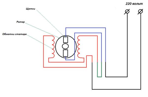
If you did everything right, the motor will start to rotate. If this does not happen, then check the engine for performance and after that draw conclusions.
Connecting the motor of a modern washing machine is quite simple, which cannot be said about old machines. Here the scheme is slightly different.
Connecting the motor of an old washing machine
Connecting the motor of an old washer is a little more complicated and will require you to find the right windings yourself with a multimeter. To find the wires, ring the motor windings and find a pair. 
To do this, switch the multimeter to measure resistance, touch the first wire with one end, and find its pair with the second in turn. Write down or remember the resistance of the winding - we will need it.
Then, similarly, find the second pair of wires and fix the resistance. We got two windings with different resistance. Now you need to determine which one is working and which is launcher. Everything is simple here, the resistance of the working winding should be less than that of the starting one.
To start an engine of this kind, you will need a button or a start relay. A button is needed with a non-fixable contact and, for example, a button from a doorbell will do.
Now we connect the engine and the button according to the scheme: But the excitation winding (OV) is directly supplied with 220 V. The same voltage must be applied to the starting winding (PO), only to start the engine for a short time, and turn it off - this is what the button is for ( SB).
We connect the OB directly to the 220V network, and connect the software to the 220V network through the SB button. 
- ON - starting winding. It is intended only for starting the engine and is activated at the very beginning, until the engine starts to rotate.
- OV - excitation winding. This is a working winding that is constantly in operation, and it rotates the engine all the time.
- SB - a button with which voltage is applied to the starting winding and, after starting the motor, turns it off.
After you have made all the connections, it is enough to start the engine from the washing machine. To do this, press the SB button and, as soon as the engine starts to rotate, release it.
In order to reverse (motor rotation in the opposite direction), you need to swap the contacts of the software winding. This will cause the motor to rotate in the opposite direction.
Everything, now the motor from the old washer can serve you as a new device.
Before starting the engine, be sure to fix it on a flat surface, because its rotational speed is quite large.