A transistor multivibrator is a square wave generator. Below in the photo is one of the oscillograms of a symmetrical multivibrator.
A symmetrical multivibrator generates rectangular pulses with a duty cycle of two. You can read more about duty cycle in the article frequency generator. We will use the operating principle of a symmetrical multivibrator to alternately turn on the LEDs.

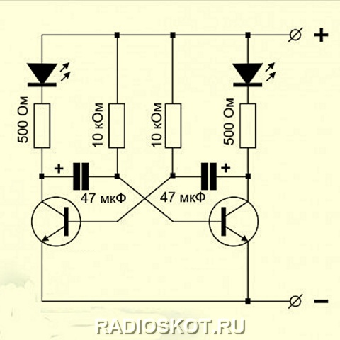
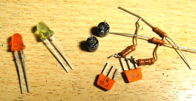
The scheme consists of:
– two KT315B (can be with any other letter)
– two capacitors with a capacity of 10 microFarads
– four, two 300 Ohm each and two 27 KiloOhm each
– two Chinese 3 Volt LEDs

This is what the device looks like on a breadboard:

And this is how it works:
To change the blinking duration of the LEDs, you can change the values of capacitors C1 and C2, or resistors R2 and R3.
There are also other types of multivibrators. You can read more about them. It also describes the operating principle of a symmetrical multivibrator.
If you are too lazy to assemble such a device, you can buy a ready-made one;-) I even found a ready-made device on Alika. You can look it up at this link.
Here is a video that describes in detail how a multivibrator works:
In this article I will explain in detail how to make a multivibrator, which is the first circuit of almost every second radio amateur. As we know, a multivibrator is an electronic device that generates electrical oscillations close to rectangular in shape, which is reflected in its name: “multi-many”, “vibro-oscillation”. In other words, a multivibrator is a relaxation-type rectangular pulse generator with resistive-capacitive positive feedback, using a two-cascade amplifier closed in a positive feedback ring. When the multivibrator operates in self-oscillation mode, periodically repeating rectangular pulses are generated. The frequency of the generated pulses is determined by the parameters of the timing circuit, the properties of the circuit and its power supply mode. The frequency of self-oscillations is also influenced by the connected load. Typically, a multivibrator is used as a pulse generator of relatively long duration, which is then used to generate pulses of the required duration and amplitude.
Multivibrator circuit operation
Symmetrical transistor multivibrator
Schematically, the multivibrator consists of two amplifier stages with a common emitter, the output voltage of each of which is applied to the input of the other. When the circuit is connected to the power source Ek, both transistors pass through the collector points - their operating points are in the active region, since a negative bias is applied to the bases through resistors RB1 and RB2. However, this state of the circuit is unstable. Due to the presence of positive feedback in the circuit, the condition?Ku>1 is satisfied and the two-stage amplifier is self-excited. The regeneration process begins - a rapid increase in the current of one transistor and a decrease in the current of the other transistor. Let, as a result of any random change in the voltages at the bases or collectors, the current IK1 of transistor VT1 increase slightly. In this case, the voltage drop across resistor RK1 will increase and the collector of transistor VT1 will receive an increase in positive potential. Since the voltage on capacitor SB1 cannot change instantly, this increment is applied to the base of transistor VT2, turning it off. At the same time, the collector current IK2 decreases, the voltage at the collector of transistor VT2 becomes more negative and, transmitted through capacitor SB2 to the base of transistor VT1, opens it even more, increasing the current IK1. This process proceeds like an avalanche and ends with transistor VT1 entering saturation mode, and transistor VT2 entering cutoff mode. The circuit enters one of its temporarily stable equilibrium states. In this case, the open state of transistor VT1 is ensured by a bias from the power source Ek through resistor RB1, and the closed state of transistor VT2 is ensured by the positive voltage on capacitor SB1 (Ucm = UB2 > 0), which is connected through the open transistor VT1 to the base-emitter gap of transistor VT2.
To build a multivibrator The radio components we need are:1. Two KT315 type transistors.
2. Two electrolytic capacitors 16V, 10-200 microfarads (The smaller the capacitance, the more often the blinking).
3. 4 resistors with a nominal value of: 100-500 ohms, 2 pieces (if you set 100 ohms, the circuit will work even from 2.5V), 10 ohms, 2 pieces. All resistors are 0.125 watt.
4. Two dim LEDs (Any color except white).
Lay6 format printed circuit board. Let's start manufacturing. The printed circuit board itself looks like this:
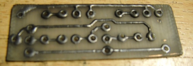
We solder two transistors, do not confuse the collector and base on the transistor - this is a common mistake.

We solder capacitors 10-200 Microfarads. Please note that 10 volt capacitors are highly undesirable for use in this circuit if you will be supplying 12 volt power. Remember that electrolytic capacitors have polarity!

The multivibrator is almost ready. All that remains is to solder the LEDs and input wires. A photo of the finished device looks something like this:

And to make everything clearer to you, here’s a video of a simple multivibrator in action:
In practice, multivibrators are used as pulse generators, frequency dividers, pulse shapers, contactless switches, and so on, in electronic toys, automation devices, computing and measuring equipment, in time relays and master devices. I was with you Boil-:D . (material was prepared upon request Demyan" a)
Discuss the article MULTIVIBRATOR
To generate rectangular pulses with frequencies above, you can use circuits that work on the same principle as the circuit in Fig. 18.32. As shown in Fig. 18.40, a simple differential amplifier is used as a comparator in such circuits.
Positive feedback in the Schmitt trigger circuit is provided by directly connecting the amplifier output to its input, i.e., the resistance of the resistor in the voltage divider is chosen equal to zero. According to formula (18.16), such a scheme should have resulted in an infinitely long period of oscillation, but this is not entirely true. When deriving this equation, it was assumed that the amplifier used as a comparator has an infinitely large gain, i.e. that the circuit switching process occurs when the input voltage difference is equal to zero. In this case, the switching threshold of the circuit will be equal to the output voltage, and the voltage on capacitor C will reach this value only after a very long time.

Rice. 18.40 Multivibrator based on a differential amplifier.
The differential amplifier circuit on the basis of which the generator is made in Fig. 18.40, has a fairly low gain. For this reason, the circuit will switch even before the difference between the amplifier's input signals reaches zero. If, for example, such a scheme is implemented as shown in Fig. 18.41, based on a linear amplifier manufactured using ESL technology (for example, based on an integrated circuit, the difference in input signals at which the circuit switches will be approximately. When the output voltage amplitude is about typical for circuits made on the basis of ESL technology, the pulse period the generated signal is equal to
The considered circuit allows you to generate a pulse voltage with a frequency of up to
A similar generator can also be made based on TTL circuits. A ready-made Schmitt trigger chip (for example, 7414 or 74132) is suitable for these purposes, since it already has internal positive feedback. The corresponding connection of such a microcircuit is shown in Fig. 18.42. Since the input current of the TTL element must flow through the Schmitt trigger resistor, its resistance should not exceed 470 Ohms. This is necessary for confident switching of the circuit at the lower threshold. The minimum value of this resistance is determined by the output load capacity of the logic element and is equal to about 100 Ohms. The Schmitt trigger thresholds are 0.8 and 1.6 V. For an output signal amplitude of about 3 V, typical for TTL-type ICs, the pulse frequency of the generated signal is
The maximum achievable frequency value is about 10 MHz.
The highest generation frequencies are achieved when using special multivibrator circuits with emitter connections (for example, microcircuits or The circuit diagram of such a multivibrator is shown in Fig. 18.43. In addition, these integrated circuits are equipped with additional final stages made on the basis of TTL or ESL circuits.
Let's consider the principle of operation of the circuit. Let us assume that the amplitude of alternating voltages at all points of the circuit does not exceed the value When the transistor is closed, the voltage at its collector is almost equal to the supply voltage. The voltage at the emitter of the transistor is the Emitter Current

Rice. 18.41. Multivibrator based on a linear amplifier made using ESL technology.

Rice. 18.42. Multivibrator based on a Schmitt trigger, made using TTL technology. Frequency

Rice. 18.43. Multivibrator with emitter connections.
transistor is equal In order for a signal of the desired amplitude to be released at the resistor, its resistance must be Then in the considered state of the circuit, the voltage at the emitter of the transistor will be equal to . During the time when the transistor is closed, the current of the left source according to the circuit flows through capacitor C. As a result, the voltage at the emitter of the transistor decreases at a rate
Transistor T opens when the voltage at its emitter decreases to the value. In this case, the voltage at the base of the transistor decreases by 0.5 V and the transistor closes, and the voltage at its collector increases to the value Due to the presence of an emitter follower on the transistor, the voltage at the collector of the transistor increases with increasing voltage also the transistor base voltage. As a result, the voltage at the emitter of the transistor increases abruptly to this value. This voltage jump through capacitor C is transmitted to the emitter of the transistor so that the voltage at this point increases abruptly from to
During the time when the transistor is closed, the current flowing through capacitor C causes the voltage at the emitter of the transistor to decrease at a rate
![]()
The transistor remains off until its emitter potential drops from value to value For a transistor this time is


 LEDs are installed on the multivibrator board
 LED flasher - symmetrical multivibrator
 The application of the symmetrical multivibrator circuit is very wide. Elements of multivibrator circuits are found in computer technology, radio measuring and medical equipment.
A set of parts for assembling LED flashers can be purchased at the following link http://ali.pub/2bk9qh . If you want to seriously practice soldering simple structures, the Master recommends purchasing a set of 9 sets, which will greatly save your shipping costs. Here is the link to purchase http://ali.pub/2bkb42 . The master collected all the sets and they started working. Success and growth of skills in soldering.
A multivibrator is the simplest pulse generator that operates in the self-oscillation mode, that is, when voltage is applied to the circuit, it begins to generate pulses.
The simplest diagram is shown in the figure below:

multivibrator circuit with transistors
Moreover, the capacitances of capacitors C1, C2 are always selected as identical as possible, and the nominal value of the base resistances R2, R3 should be higher than the collector ones. This is an important condition for proper operation of the MV.
How does a transistor-based multivibrator work? So: when the power is turned on, capacitors C1 and C2 begin to charge.
The first capacitor in the chain R1-C1-transition BE of the second body.
The second capacitance will be charged through the circuit R4 - C2 - transition BE of the first transistor - housing.
Since there is a base current on the transistors, they almost open. But since there are no two identical transistors, one of them will open a little earlier than its colleague.
Let's assume that our first transistor opens earlier. When it opens, it will discharge capacity C1. Moreover, it will discharge in reverse polarity, closing the second transistor. But the first one is in the open state only for the moment until capacitor C2 is charged to the supply voltage level. At the end of the charging process C2, Q1 is locked.
But by this time C1 is almost discharged. This means that a current will flow through it, opening the second transistor, which will discharge capacitor C2 and will remain open until the first capacitor is recharged. And so on from cycle to cycle until we turn off the power from the circuit.
As is easy to see, the switching time here is determined by the capacitance rating of the capacitors. By the way, the resistance of the basic resistances R1, R3 also contributes a certain factor here.
Let's return to the original state, when the first transistor is open. At this moment, capacitance C1 will not only have time to discharge, but will also begin to charge in reverse polarity along the circuit R2-C1-collector-emitter of open Q1.
But the resistance of R2 is quite large and C1 does not have time to charge to the level of the power source, but when Q1 is locked, it will discharge through the base chain of Q2, helping it to open faster. The same resistance also increases the charging time of the first capacitor C1. But the collector resistances R1, R4 are a load and do not have much effect on the frequency of pulse generation.
As a practical introduction, I propose to assemble, in the same article the design with three transistors is also discussed.

multivibrator circuit using transistors in the design of a New Year's flasher
Let's look at the operation of an asymmetrical multivibrator using two transistors using the example of a simple homemade amateur radio circuit that makes the sound of a bouncing metal ball. The circuit works as follows: as capacitance C1 discharges, the volume of the blows decreases. The total duration of the sound depends on the value of C1, and capacitor C2 sets the duration of pauses. Transistors can be absolutely any p-n-p type.

There are two types of domestic micro multivibrators - self-oscillating (GG) and standby (AG).
Self-oscillating ones generate a periodic sequence of rectangular pulses. Their duration and repetition period are set by the parameters of external elements of resistance and capacitance or the level of control voltage.
Domestic microcircuits of self-oscillating MVs, for example, are 530GG1, K531GG1, KM555GG2 You will find more detailed information on them and many others in, for example, Yakubovsky S.V. Digital and analogue integrated circuits or ICs and their foreign analogues. Directory in 12 volumes edited by Nefedov
For waiting MVs, the duration of the generated pulse is also set by the characteristics of the attached radio components, and the pulse repetition period is set by the repetition period of the trigger pulses arriving at a separate input.
Examples: K155AG1 contains one standby multivibrator that generates single rectangular pulses with good duration stability; 133AG3, K155AG3, 533AG3, KM555AG3, KR1533AG3 contains two standby MVs that generate single rectangular voltage pulses with good stability; 533AG4, KM555AG4 two waiting MVs that form single rectangular voltage pulses.
Very often in amateur radio practice they prefer not to use specialized microcircuits, but to assemble it using logical elements.
The simplest multivibrator circuit using NAND gates is shown in the figure below. It has two states: in one state DD1.1 is locked and DD1.2 is open, in the other - everything is the opposite.

For example, if DD1.1 is closed, DD1.2 is open, then capacitance C2 is charged by the output current of DD1.1 passing through resistance R2. The voltage at the DD1.2 input is positive. It keeps DD1.2 open. As capacitor C2 charges, the charging current decreases and the voltage across R2 drops. At the moment the threshold level is reached, DD1.2 begins to close and its output potential increases. The increase in this voltage is transmitted through C1 to output DD1.1, the latter opens, and the reverse process develops, ending with complete locking of DD1.2 and unlocking of DD1.1 - the transition of the device to the second unstable state. Now C1 will be charged through R1 and the output resistance of the microcircuit component DD1.2, and C2 through DD1.1. Thus, we observe a typical self-oscillatory process.
Another simple circuit that can be assembled using logic elements is a rectangular pulse generator. Moreover, such a generator will operate in self-generation mode, similar to a transistor one. The figure below shows a generator built on one logical digital domestic microassembly K155LA3

multivibrator circuit on K155LA3
A practical example of such an implementation can be found on the electronics page in the design of the calling device.
A practical example of the implementation of the operation of a waiting MV on a trigger in the design of an optical lighting switch using IR rays is considered.