Reading 5 min.
Steering gear - it is this mechanism that has been helping drivers turn the steering wheel for more than a decade, you can say he is the father of the power steering.
There is a mechanism in the car that was invented at the very beginning of the automotive industry - this. The main purpose of this mechanism is the same as that of the well-known power steering, namely, to help the driver turn the steering wheel, compensating for the resistance of the wheels. In other words, if the car did not have this important device, with each turn of the steering wheel, the driver would have to make quite a lot of effort.
This mechanism is made as a separate unit of the steering system. It consists either of gears, or is presented in the form of a worm shaft.
The mechanism of operation and the device of the gearbox
This text will be devoted to the general principle of operation of the gearbox, and the analysis of this mechanism using a specific example, namely on the famous UAZ 469 car or, as it is also called, the “loaf”.
To begin with, the vast majority, if not all, of gearboxes are made from solid cast iron and welded with steel. The use of these materials gives the necessary parameters of rigidity and strength to this mechanism, due to the specifics of its device. Under the soldered cast iron are fairly simple transmission elements: gears, shafts, bearings, belts, gears, etc. Complete sets are also possible, in which the location of the lubricating element inside the mechanism is provided. This allows you to lubricate the gears and bearings inside the UAZ Loaf gearbox.
Today, many different configurations are known in which the steering gear is made, but the worm gear mechanism remains the most common.
It is included in the package of absolutely all modern cars with a gearbox system on the steering wheel, including the UAZ 469 (loaf). These systems involve the transmission of torque using a worm gear, consisting mainly of a special worm screw and a toothed worm wheel.
The so-called "worm" installed in the UAZ 469 gearbox is made as a cast part from the strongest alloy. Outwardly, it looks like the core in the well-known meat grinder, speaking in terms, the thread on the worm is made in a trapezoidal shape. As for the worm wheel, it is not much different from the usual gear, but the thread on this element is made especially carefully and is literally jewelerly adjusted to the shape of the worm thread.
Gears for gearboxes of such power as in the UAZ 469 loaf are made of durable materials, usually either cast iron, which does not tear under great effort, or a strong steel alloy, the core is made of them. The teeth are made of special anti-friction materials of increased strength. Worm gear is most effective in machines where high torque is expected combined with low angular velocity.
Advantages and disadvantages of the steering gear
The advantages that the UAZ 469 gearbox has include four factors:
- Self-braking;
- High ratio ratio, despite the fact that only two parts are used;
- Quite a small level of noise generated during the operation of the mechanism;
- Smooth move.

Also, a significant advantage of a worm-type gearbox, when compared with a gear one, is that the contact between the links is carried out along the entire length of the line, and not at one point, like a gear one. Also a huge plus is the compactness of the worm gear, despite the fact that the gear ratio is identical for both systems.
As for the cons, they are quite significant:
- Such a gearbox has a high level of wear;
- It generates a large amount of heat, due to the large friction force of the parts;
- The mechanism jams quite often;
- It also produces a relatively low efficiency.
In order for the mechanism to jam less and wear out less, it must be constantly adjusted, looked after, and all the nuances must be observed during assembly. However, in this case, it will not be possible to completely get rid of the shortcomings, even if we take into account the newer UAZ Patriot car.
The nuances of repair and wear of the gearbox
In our life, nothing is forever, no matter how sad it may sound. Any, even the most reliable mechanism fails, breaks down and it’s good if after that it needs to be repaired. The worm gearbox installed on the UAZ loaf or Patriot is no exception.
The most common nuisance faced by car owners with this steering mechanism is gearbox leakage. It can leak for two reasons:
- Input shaft corrosion;
- Seal leakage.
In both cases, the main symptom of the “illness” is a little leak, which can be found directly under your UAZ 469 loaf. But the complexity of the repair will be different. In the first case, you will have to grind the shaft and carry out the thermal spraying operation. The second problem is easier to solve, you just have to change the gaskets and cuffs on the stuffing box, the old ones can just be thrown away.
Another problem in the gearboxes on the UAZ loaf and Patriot is the feeling that the steering wheel has become hard to turn. In this case, you will have to visit the nearest service station, where they measure the level of effort applied when turning the steering wheel, and they will give a verdict. It is better not to carry out repairs with your own hands, because you need special equipment and, of course, knowledge.
conclusions
In view of all of the above, we can conclude that the gearbox on the UAZ 469 and the newer Patriot model is a fairly reliable thing and the significance of this mechanism is dictated by years of operation. But, although it deserves respect, the system also has disadvantages that you definitely need to know and take into account.
Produce to eliminate the gaps that appear during the running-in of the working pair of the worm-roller and its wear during the operation of the car. The working pair of the steering mechanism is designed in such a way that when the roller is in the position corresponding to the movement of the vehicle in a straight line, the engagement gap is practically zero. As the wheel turns in one direction or another, the gap in the engagement gradually increases, reaching its maximum value in the extreme positions of the roller. The condition of the steering mechanism is considered normal and does not require adjustment if the free play of the steering wheel in the straight ahead position does not exceed 10 °, which corresponds to 40 mm when measured at the wheel rim. If the steering wheel play is more than specified, then, before proceeding with the adjustment of the steering mechanism, make sure that the crankcase mounting bolts are tight and the drive swivel joints are in good condition.
Units and parts of the UAZ-469 steering gear, spare parts: 1 - steering gear housing; 2 - bushing; 3 - stuffing box; 4 - bipod: 5 - washer; 6 - nut; 7 - stuffing box; 8 and 14 - worm bearings; 9 - cork; 10 - shaft of the steering UAZ-469 mechanism; 11 - worm; 12 - lower crankcase cover; 13 - gaskets; 15 - roller axis; 16 - bipod shaft roller; 17 - bipod shaft with roller and bearing; 18 - crankcase mounting bolts; 19 - hinge; 20 - retaining ring; 21 - protective washer; 22 - spring; 23 - spacer sleeve; 24 - bearings; 25 - horn wire; 26 - contact sleeve; 27 - screw; 28 and 29 - plastic bushings; 30 - steering wheel; 31 - steering shaft; 32 - adjusting screw; 33 - cap nut; 34 - lock washer; 35 - pin; 36 - weaving shaft bearing; 37 - side cover of the crankcase; 38 - gasket; 39 - bushing.
Adjust the tightening of the bearings of the UAZ-469 worm using gaskets 13 installed between the crankcase and the lower cover of the steering gear housing, in the following sequence:
1. Remove the steering gear from the vehicle.
2. Drain the oil from the crankcase.
3. Clamp the steering mechanism in a vise.
4. Loosen cap nut 33 and remove lock washer 34 from adjusting screw 32.
5. Turn away bolts of fastening of a lateral cover 37 crankcases.
6. Remove the shaft 17 of the bipod together with the cover with light blows of a copper or aluminum drift on the end of the shaft and carefully remove the gasket 38.
7. Turn away bolts of fastening of the bottom cover of a crankcase and remove the bottom cover 12.
8. Carefully peel off and remove the thin paper spacer 13.
9. Replace the bottom cover, tighten the bolts and check the axial movement of the worm.
10. If axial movement remains, then remove the bottom cover again, remove the thick gasket, and install the previously removed thin one in its place. Do not remove more than one gasket.
If a radial play appears in the hinge (axial movement of the cross in the bearings), perform an additional centering of the bearings in the fork ears. Carry out the punching in such a way as to prevent the bearing cup from collapsing. The bearings of the cross are filled with Litol-24 grease during assembly at the factory and it is not required to add it in operation. Next: Possible malfunctions of the UAZ-469 steering.
- Technical characteristics of UAZ-469, UAZ-469B
- Engine UAZ-469, UAZ-469B
- Transmission UAZ-469, UAZ-469B
- UAZ-469 controls
- Preparation for work UAZ-469
- Engine mount UAZ-469
- The crank mechanism of the UAZ-469 engine
- Gas distribution mechanism of the UAZ-469 engine
- Lubrication system UAZ-469
- Engine crankcase ventilation system UAZ-469
- UAZ-469 engine power system
- Carburetor K-129V
- UAZ-469 engine exhaust system
- Engine cooling system UAZ-469
- Engine preheater UAZ-469
- UAZ-469 engine malfunctions
- Clutch UAZ-469
- Gearbox UAZ-469
- Transfer box UAZ-469
- Cardan UAZ-469
- Rear axle UAZ-469
- Rear axle UAZ-469B
- Front drive axle UAZ-469
- Frame UAZ-469
- Suspension UAZ-469
- Steering UAZ-469
- Brakes UAZ-469
- Electrics UAZ-469
- Generator UAZ-469
- Voltage regulator PP132
- Battery UAZ-469
- UAZ-469 ignition system
- Starter UAZ-469
- Lighting, light and sound alarm system UAZ-469
- Instrumentation UAZ-469
- Tools and accessories UAZ-469
- Body UAZ-469
- Marking UAZ-469
- Maintenance UAZ-469
- Lubricants UAZ-469 and UAZ-469B
Device and work steering gear UAZ loaf
There is a mechanism in the car that was invented at the very beginning of the automotive industry - this steering gear. The main purpose of this mechanism is the same as that of the well-known power steering, namely, to help the driver turn the steering wheel, compensating for the resistance of the wheels. In other words, if the car did not have this important device, with each turn of the steering wheel, the driver would have to make quite a lot of effort.
This mechanism is made as a separate unit steering systems. It consists either of gears, or is presented in the form of a worm shaft.
The mechanism of operation and the device of the gearbox

Device steering gear UAZ
This text will be devoted to the general principle of operation of the gearbox, and the analysis of this mechanism using a specific example, namely on the famous car “UAZ 469” or as it is also called - “ loaf”.
To begin with, the vast majority, if not all, of gearboxes are made from solid cast iron and welded with steel. The use of these materials gives the necessary parameters of rigidity and strength to this mechanism, due to the specifics of its device. Under the soldered cast iron are fairly simple transmission elements: gears, shafts, bearings, belts, gears, etc. Complete sets are also possible, in which the location of the lubricating element inside the mechanism is provided. This allows you to lubricate the gears and bearings inside the UAZ gearbox Loaf”.
Today, there are many different configurations in which it is made steering gear, however, the worm gear mechanism remains the most common.
It is included in the package of absolutely all modern cars with a gearbox system on the steering wheel, including the UAZ 469 ( loaf). These systems involve the transmission of torque using a worm gear, consisting mainly of a special worm screw and a toothed worm wheel.
The so-called “worm” installed in the UAZ 469 gearbox is made as a cast part from the strongest alloy. Outwardly, it looks like the core in the well-known meat grinder, speaking in terms, the thread on the worm is made in a trapezoidal shape. As for the worm wheel, it is not much different from the usual gear, but the thread on this element is made especially carefully and is literally jewelerly adjusted to the shape of the worm thread.
UAZ - Repair steering columns ( steering reducer)
Disassembly, troubleshooting and adjustment. As well as a comparison with other steering columns.
Removing the steering wheel from the UAZ car
Withdrawal helmsman wheels from car UAZ.
Gear wheels for gearboxes of such power as in UAZ 469 loaf they are made of durable materials, usually either cast iron, which does not tear under great effort, or a durable steel alloy, the core is made of them. The teeth are made of special anti-friction materials of increased strength. Worm gear is most effective in machines where high torque is expected combined with low angular velocity.
Advantages and disadvantages steering gear
The advantages that the UAZ 469 gearbox has include four factors:
- Self-braking;
- High ratio ratio, despite the fact that only two parts are used;
- Quite a small level of noise generated during the operation of the mechanism;
- Smooth move.

Also, a significant advantage of a worm-type gearbox, when compared with a gear one, is that the contact between the links is carried out along the entire length of the line, and not at one point, like a gear one. Also a huge plus is the compactness of the worm gear, despite the fact that the gear ratio is identical for both systems.
As for the cons, they are quite significant:
- Such a gearbox has a high level of wear;
- It generates a large amount of heat, due to the large friction force of the parts;
- The mechanism jams quite often;
- It also produces a relatively low efficiency.
In order for the mechanism to jam less and wear out less, it must be constantly adjusted, looked after, and all the nuances must be observed during assembly. However, even in this case, it will not be possible to completely get rid of the shortcomings, even if we take into account the newer UAZ Patriot car.
The nuances of repair and wear of the gearbox
In our life, nothing is forever, no matter how sad it may sound. Any, even the most reliable mechanism fails, breaks down and it’s good if after that it needs to be repaired. Worm gear mounted on UAZ loaf or Patriot is no exception.
The most common nuisance faced by car owners with this steering mechanism is gearbox leakage. It can leak for two reasons:
- Input shaft corrosion;
- Seal leakage.
In both cases, the main symptom of the “illness” is a little leak, which can be found directly under your UAZ 469 loaf. But the complexity of the repair will be different. In the first case, you will have to grind the shaft and carry out the thermal spraying operation. The second problem is easier to solve, you just have to change the gaskets and cuffs on the stuffing box, the old ones can just be thrown away.
Another problem in UAZ gearboxes loaf and Patriot - this is the feeling that the steering wheel has become hard to turn. In this case, you will have to visit the nearest service station, where they measure the level of effort applied when turning the steering wheel, and they will give a verdict. It is better not to carry out repairs with your own hands, because you need special equipment and, of course, knowledge.
conclusions
In view of all of the above, we can conclude that the gearbox on the UAZ 469 and the newer Patriot model is a fairly reliable thing and the significance of this mechanism is dictated by years of operation. But, although it deserves respect, the system also has disadvantages that you definitely need to know and take into account.
Post Views: 6
As you know, the direction of movement of modern cars is controlled using the steering wheel. The basis of the steering is a steering mechanism hidden in the bowels of the car. About what a steering mechanism is, about its varieties, device and principles of operation will be discussed in this article.
chivaya movement of steering rods and, accordingly, the rotation of the wheels. The worm gear has good characteristics, dampens the steering mechanism (does not transmit vibrations from the wheels to the steering wheel) and provides good handling. However, it is expensive and has a complex device, so it is practically not used on modern cars. Screw mechanism The screw mechanism in general terms resembles a worm gear: a screw is fixed on the steering shaft, on which a nut with a rack is put on, which, in turn, is connected to a sector with a bipod. Between the screw and the nut, directly in the thread, there are balls, which achieves the replacement of sliding friction by rolling friction. When the steering shaft is turned, the screw comes into rotation and shifts the nut, the rail on the outer side of the nut deflects the sector, and the bipod and tie rods deflect along with it. The screw mechanism provides better performance than the worm, but it is also quite complex and has a high price. That's why tacosRice. 5.1. The steering mechanism of cars of the UAZ-31512 family:
1 - crankcase; 2.39 - bushings; 3 - cuff; 4 - bipod; 5 - washer; 6.33 - nuts; 7 - stuffing box; 8.14 - bearings; 9 - plug; 10 – a shaft of the steering mechanism; 11 - worm; 12 - bottom cover; 13 - shims; 15 – roller axis; 16 - bipod shaft roller; 17 - bipod shaft; 18 - crankcase mounting bolts; 19 - hinge; 20 - retaining ring; 21 - protective washer; 22 - spring; 23 - expanding ring; 24 - bearings; 25 – a wire of a sound signal; 26 - contact sleeve; 27 - screw; 28.29 - plastic bushings; 30 - steering wheel; 31 – steering shaft; 32 - adjusting screw; 34 - lock washer; 35 - pin; 36 - bearing; 37 - side cover of the crankcase; 38 - gasket

Rice. 5.3. Steering drive for cars of the UAZ-31512 family:
1 – steering linkage levers; 2 - transverse steering rod; 3 – bipod of the steering mechanism; 4 - bipod thrust; 5 – lever of a rotary fist

Rice. 5.4. Steering gear for cars of the UAZ-3741 family:
1 – longitudinal steering rod; 2 – lever of longitudinal steering draft; 3, 6 – steering linkage levers; 4, 7 – tie rod ends; 5 – transverse steering rod
The steering of the car consists of a worm-roller type steering mechanism with a steering wheel (Fig. 5.1, 5.2) and a steering gear (Fig. 5.3, 5.4).

Rice. 5.5. Steering mechanism type screw-ball nut-sector:
1 - steering housing; 2 - shaft-sector; 3 - nut-rail; 4 - balls; 5,21,24 - retaining rings; 6,9,20,25 - protective covers; 7 - universal joint; 8 - bushing; 10 - cuff; 11 - screw bearings; 12 – bolts of fastening of the steering mechanism to a frame; 13 - shims; 14 - screw; 15 - bipod; 16 - lower crankcase cover; 17, 23, 26 - sealing rings; 18 - nut; 19 - washer; 22 - rollers; 27 - protective ring; 28 - ring of the shaft-sector support; 29 - filler plug; 30 – ball guide chute; 31 - pad of the ball guide; 32 - drain plug; 33 - plug

Rice. 5.6. Steering gear with hydraulic booster:
1 - nut; 2, 5, 6, 19, 21, 22, 35, 39 - sealing rings; 3 - glass; 4, 10 - thrust bearings; 7 - piston-rail; 8 - screw; 9 - crankcase; 11 - fitting of the discharge hose; 12 - drain hose fitting; 13 - sleeve; 14 - cuff; 15 - torsion bar; 16, 38 - pins; 17 - ball guide; 18 - balls; 20 - channel in the crankcase; 23 - bipod; 24 - bipod nut; 25 – protective bottom cover; 26 - retaining rings; 27 - adjusting washers; 28 - bipod shaft supports; 29 - rollers; 30 - bipod shaft; 31 - top protective cover; 32 - rotor; 33 - protective cap; 34 - distributor housing; 36 - channel in the distributor housing; 37 - bolts for fastening the distributor housing to the crankcase
On individual vehicles of the UAZ-31512 family, a steering gear of the screw-ball nut-sector type is installed without hydraulic booster (Fig. 5.5) or with hydraulic booster (Fig. 5.6).
Maintenance steering differs only in the adjustment of the steering gears.
Timely tighten the bolts securing the steering gear housing to the frame side member, check the fastening of the steering rod pins, bipod and steering knuckle lever. Check the free play of the steering wheel, adjust the steering gear, lubricate the tie rod joints and add oil to the steering gear housing or oil reservoir (in the case of a power steering gear) according to the lubrication table.

Rice. 5.7. Tie rod joint:
1 - plug; 2 - spring; 3 - heel; 4 - lower spherical washer; 5 – top spherical washer; 6 - protective ring; 7 - spring cap; 8 - cotter pin; 9, 13 - nuts; 10 - ball pin; 11 - cracker; 12 - tip; 14 - thrust
If a gap appears in the steering rod joints, screw the plug 1 up to the stop (Fig. 5.7), and then unscrew it by 1/2 turn and tighten it in this position.
Periodically check the tightness of the tie rod nuts.
Do not allow gaps in the tapered joints of the levers and pins.
To eliminate them, unpin the nut and tighten it until it stops.
Untimely tightening of these connections causes wear of the conical holes in the levers, which will require replacement of parts.
When servicing vehicles of the UAZ-31512 family, pay attention to the condition of the mounting of the bearings in the forks of the steering joint.
If a radial clearance appears in the hinge (axial movement of the cross in the bearings), perform an additional reaming of the bearings in the lugs of the forks. Carry out the punching in such a way as to prevent the bearing cup from collapsing.
The bearings of the cross are filled with Litol-24 grease during assembly at the factory and it is not required to add it in operation.
Maintenance of the power steering system consists in checking the tension of the pump drive belt, checking the tightness of the hoses and their connections, checking for leaks in the pump and steering gear seals, checking the level and changing the oil in the oil reservoir.
Steering wheel free play check
The condition of the steering mechanism is considered normal and does not require adjustment if the free play of the steering wheel in the straight ahead position does not exceed 10 degrees, which corresponds to 40 mm when measured on the steering wheel rim.
In the presence of a power steering, check the free play of the steering wheel when the engine is idling, shaking the steering wheel in both directions until the front wheels start turning.
In the case of a steering mechanism without hydraulic booster, check the free play with a force of 7.5 N (0.75 kgf) on the steering wheel rim in both directions. If the free play is more than specified, then, before proceeding with the adjustment of the steering mechanism, check the mounting of the steering mechanism, the condition of the steering rod joints, the condition of the steering column hinge, the tightening of the bolts for fastening the forks of the hinges and the absence of play in the spline connection of the cardan shaft, the tightening of the bipod fastening nuts and lever, steering wheel mount.
Power steering pump drive belt tension
With normal belt tension, its deflection in the middle between the pulleys of the crankshaft and the pump, when the belt is pressed with a force of 39 N (4 kgf), should be 12–17 mm. If necessary, tension the belt by moving the pump along the bracket for its attachment to the engine. To do this, loosen the bolts securing the pump to the bracket, move the pump with the adjusting screw until the belt tension is normal and tighten the pump mounting bolts. Replace the belt if it is damaged or overstretched.
Checking the level and changing the power steering oil
The front wheels must be straight when checking the oil level in the oil tank.
Add oil to the level of the grid of the oil tank filler filter or above it by no more than 5 mm. The oil must be pre-filtered through a filter with a filtration fineness of not more than 40 microns.
All-weather grade "P" oil is used as a working fluid.
The volume of the filled oil is 1.1 l.
Change the oil and filter in the oil tank every 100,000 km or 2 years of operation.
Change the oil also when repairing or adjusting the steering mechanism.
Filling system
1. Remove the oil tank cap, fill in oil until it appears above the filter mesh (no more than 5 mm).
2. Without starting the engine, turn the steering wheel or the input shaft of the mechanism from lock to lock until air bubbles come out of the oil in the tank. Add oil to the tank. When pumping, disconnect the bipod link from the bipod or hang the front wheels.
3. Start the engine while adding oil to the tank.
Note In case of abundant foaming of the oil in the tank, which indicates the ingress of air into the system, turn off the engine and let the oil settle for at least 20 minutes (until air bubbles come out of the oil). Inspect the places where the hoses are connected to the units of the hydraulic booster system and, if necessary, eliminate leaks.
4. Let the engine run for 15–20 seconds and bleed the hydraulic booster system to remove residual air from the steering mechanism by turning the steering wheel from lock to lock, without stopping in extreme positions, three times in each direction.
5. Add oil to the tank if necessary.
6. Close the tank with a lid and tighten the lid nut by hand.
7. Attach the bipod link, tighten and cotter the ball stud nut.
Servicing the flow and relief valves of the pump
If the flow and safety valves are dirty, flush them.
For this:
1. Unscrew the plug located above the pump outlet.
2. Remove the spring and spool of the flow valve, and reinstall the plug to prevent oil from escaping.
3. Flush the spool and the safety valve that is installed inside the spool.
4. Reassemble in reverse order.
Worm-roller steering adjustment
The steering mechanism must be adjusted to eliminate the gaps that appear between the worm and the roller.
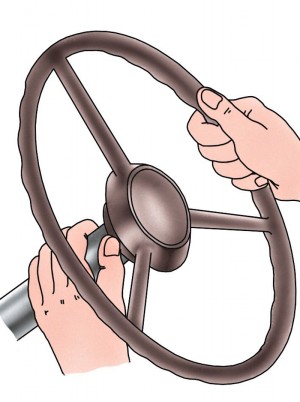
Rice. 5.8. Checking the axial clearance in the worm bearings
Start the adjustment by checking the axial clearance in the worm bearings.
To do this, grasp the column with your palm so that your thumb touches the end of the steering wheel hub and turn the steering wheel in both directions at a certain angle (Fig. 5.8). When the worm bearings are worn, the finger will feel the axial movement of the steering wheel hub relative to the column tube. If there is no axial movement of the worm, then adjust only the engagement of the roller with the worm.
Worm bearing adjustment ) use gaskets 13 (see Fig. 5.1) installed between the crankcase and the bottom cover of the steering gear housing in the following order:
1. Remove the steering gear from the vehicle.
2. Drain the oil from the crankcase.
3. Fix the steering mechanism in a vise.
4. Loosen nut 33 and remove lock washer 34 from adjusting screw 32.
5. Turn away bolts of fastening of a lateral cover 37 crankcases.
6. Lightly hitting the end of the bipod shaft 17 with a copper or aluminum drift, remove the bipod shaft together with the roller and cover and carefully remove the gasket 38.
7. Turn away bolts of fastening of the bottom cover 12 crankcase and remove a cover.
8. Carefully peel off and remove the thin paper spacer 13.
9. Replace the bottom cover, tighten the bolts and check the axial movement of the worm.
10. If axial movement remains, remove the bottom cover again, remove the thick gasket, and install the previously removed thin one in its place. Do not remove more than one pad
11. By rotating the worm 11, finally check the tightening of bearings 8 and 14. With the correct tightening of the worm roller bearings, the force required to turn the steering wheel should be 2.2–4.5 N (0.22–0.45 kgf) (without installed bipod shaft).
Check the tightening of the bearings using a dynamometer (Fig. 5.9).

Rice. 5.9. Checking the tightness of the worm bearings with a dynamometer
Adjustment of the engagement of the roller with the worm cars of the UAZ-31512 family ( Adjustment on cars of the UAZ-3741 family is carried out similarly) in the following order:
1. Set the steering wheel to the position corresponding to the movement of the car in a straight line.
2. Disconnect the tie rod from the bipod.
3. Unscrew nut 33 (see Fig. 5.1) and remove lock washer 34 from adjusting screw 32.
4. Turning the adjusting screw 32 clockwise, eliminate the gap in the engagement.
5. Put on the lock washer. If the hole in the washer does not line up with the pin, turn the adjusting screw until the hole in the washer lines up with the pin.
6. Screw the nut 33 onto the adjusting screw and, shaking the steering arm by hand, check that there is no gap in the engagement.
7. Check the effort needed to turn the steering wheel. The steering wheel should turn freely from the middle position, corresponding to the movement in a straight line, with a force of 9–16 N (0.9–1.6 kgf) applied to the steering wheel. In the absence of a special device to check the force required to turn the steering wheel, use a dynamometer.
8. Connect the link to the bipod
Adjustment of the steering gear type screw-ball nut-sector
To adjust the steering mechanism, remove it together with the bipod from the vehicle.
Fasten the steering gear with the splined end of the screw 14 (see Fig. 5.5) up, the axis of the screw 14 should take a vertical position.
1. Using a dynamometer, measure the moment of turning the screw 14 in the middle and in the extreme positions of the sector shaft
2. The middle position of the shaft-sector is found by turning the screw 2.5 turns from any extreme. To measure the moment of turning the screw in the extreme position of the shaft-sector, it is necessary to turn the shaft-sector from the stop in the extreme position by turning the screw by 1/2 turn and measure the value of the torque by turning the screw for one turn. With the correct tightening of the bearings and the absence of a gap in the engagement of the rack nut and the sector shaft, the moment of turning the shaft in the middle position of the sector shaft should be 1.6–2.5 N m (0.16–0.25 kgf m), in the extreme position of the shaft-sector, the moment should decrease to 0.8–1.2 N m (0.08–0.12 kgf m).
3. If the moment of turning the screw in the extreme positions is less than the specified one, it is necessary to adjust the tightening of the bearings 11 of the screw.
Screw bearing tightening adjustment
1. Install the steering mechanism with the bottom cover 16 (see Fig. 5.5) up and secure in this position.
2. Turn away bolts of fastening of a cover and remove a cover 16.
3. Remove one of the thin spacers 13 (0.05 mm thick).
4. Replace the cover, tighten the bolts, turn the steering mechanism over with the splined end of the screw 14 up and again measure the torque of the screw in the extreme positions.
5. If the required torque value is not reached, remove the 0.1 mm or 0.15 mm thick gasket in the same sequence, and reinstall the previously removed gasket. At least three 0.05 mm thick shims are installed in the steering mechanism, and 0.1 mm, 0.15 mm and 0.5 mm thick shims can also be installed, the number of which is determined by the assembly needs. It is not recommended to remove more than one gasket with a thickness of 0.05 mm if thicker gaskets are available.
6. Finally check the moment of turning the screw in the extreme positions of the sector shaft.
If, when checking the moment of turning the screw, it turns out that the moment in the extreme positions of the sector shaft corresponds to the recommended value, and the moment in the middle position of the sector shaft is lower than recommended, the engagement of the nut-rack 3 and the sector shaft 2 should be adjusted.
An additional sign of the need to adjust the engagement can be a gap, which is noticeable when the sector shaft swings by the bipod in the middle position of the sector shaft.
Gearing adjustment do it in the following order:
1. If on the ring mechanism 28 (see Fig. 5.5) the sector shaft supports are locked by punching the shoulder into the crankcase hole, remove the plugs 33 of the holes and straighten the shoulder with a barb and a hammer, without applying excessively strong blows. If these rings are locked with screws, loosen them.
2. Remove protective covers 20 and 25. When locking the rings with a punch, the bipod must also be removed.
3. Eliminate the gap in the engagement by turning the rings 28 of the sector shaft supports counterclockwise, when viewed from the side of the sector shaft splines. In this case, the rings of the shaft-sector supports must rotate at the same angle.
4. Check the moment of turning the screw in the middle position of the sector shaft.
5. When the torque of turning the screw in the middle position of the recommended value is reached, lock the rings of the sector shaft supports by punching the collar into the crankcase holes or by tightening the lock screws and lock nuts.
6. Install protective covers 20 and 25, plugs 33, bipod. Pre-tighten the bipod mounting nut. Make the final tightening of the bipod nut after installing the steering mechanism on the vehicle and attaching the bipod rod to the bipod.
Power steering adjustment
The steering gear must be removed from the vehicle in order to be adjusted.
For this:
1. Disconnect the pressure and drain hoses from the steering gear and secure the hoses in such a way as to prevent the complete leakage of oil from the hydraulic system.
2. Loosen the nut and remove the wedge screw from the yoke, remove the yoke from the mechanism.
3. Disconnect the bipod link from the bipod.
4. Turn away bolts of fastening and remove the steering mechanism.
Steering gear adjustment perform in the following sequence:
1. Fix the steering mechanism in a vise so that the discharge and drain holes are at the bottom. While manually turning the input shaft of the steering mechanism, drain the oil from the mechanism.
2. Lightly pressing the input shaft along its axis with your hand, shake the bipod. If axial movement of the input shaft is felt, adjust the screw bearing preload.
For this:
- using a beard and a hammer, carefully, without applying excessively strong blows, straighten the bead of the glass 3 (see Fig. 5.6), fixed in the grooves of the crankcase wall 9;
– by turning glass 3 clockwise, eliminate the backlash;
– check the moment of rotation of the input shaft, which should be no more than 3 Nm (0.3 kgfm). Measure the moment for no more than one revolution of the input shaft from any extreme position;
- screw the edge of the glass into the grooves of the crankcase wall
3. If the axial movement of the rotor is not felt or eliminated, and in the middle position of the bipod shaft when swinging the bipod, there is a gap, adjust the gearing.
For this:
– unscrew nut 24 and remove bipod 23;
– remove top 31 and bottom 25 protective covers;
– remove retaining rings 26 and adjusting washers 27;
- straighten the adjusting washers;
- simultaneously turning the supports 28 of the bipod shaft counterclockwise (when viewed from the side of the splined end of the bipod shaft), eliminate the gap in the engagement. Make adjustments in the position of the bipod shaft corresponding to the middle position of the gear sector;
- check the moment of turning the bipod shaft, which should be within 35–45 N m (3.5–4.5 kgf m) when the bipod shaft passes through the middle position. If the backlash cannot be eliminated after adjusting the bearing preload and the gear gap, then the backlash is caused by wear on the ball screw. In this case, the steering mechanism must be repaired;
- install the adjusting washers, bend one of the mustaches in both adjusting washers into the groove of the bipod shaft support and install the retaining rings.
4. Install the steering gear on the vehicle, install the bipod and hand-tighten the bipod nut.
5. Connect the cardan shaft yoke, the discharge and drain hoses, avoiding their twisting and sharp bends, fill the hydraulic system with oil (see above).
6. Attach the bipod link, tighten and cotter the ball stud nut, tighten the bipod nut.
Repair
When repairing the steering, use the data in Table. 5.1.
Removal and disassembly of the tie rod do it in the following order:
1. Loosen the steering link pin nuts.
2. Turn away nuts and press out adaptation fingers from levers.
3. Remove spring caps 7, rubber protective rings 6 and spherical washers 4 and 5 from fingers 10 (see Fig. 5.7).
4. Fix the rod in a vice, unscrew the lock nuts 1 (Fig. 5.10) and 3 and unscrew the tips 4 and the adjusting fitting 2.
5. Unscrew the threaded plug (Fig. 5.7) of the tip and remove the spring 2, the heel 3, the pin 10 and the cracker 11.

Rice. 5.10. Tie Rod End:
1 – nut with left thread; 2 - adjusting fitting; 3 – nut with right-hand thread; 4 - tip
Thrust Assembly do it in reverse order.
Replace the finger complete with cracker. It is not recommended to replace only the finger, since the rusk sphere wears out unevenly and when replacing one finger, it is not possible to achieve good mating between the finger and rusk spheres.
Before assembly, lubricate the hinge parts according to the lubrication table. When installing the screw plug, screw it in until it stops, and then unscrew it 1/2 turn and tighten it in this position.
Removal, disassembly and assembly of bipod traction produced in a similar way.
Tightening torques for main steering connections, N m (kgf m):
Steering wheel nut ..... 64–78 (6.5–8.0)
Bracket stud nuts (column mounting stepladders) ..... 18–25 (1.8–2.5)
Nut of fastening of forks of the hinge of a steering shaft..... 20–25 (2,0–2,5)
Bolts for fastening the crankcase to the frame of cars of the family:
UAZ-31512.....55-78 (5.6-8.0)
UAZ-3741.....55-61 (5.6-6.2)
Bipod nut ..... 196–275 (20–28)
Tie rod lock nuts ..... 103–128 (10.5–13.0)
Nut of fastening of a spherical finger..... 49–69 (5–7)
Steering gear without hydraulic booster
Removal and disassembly of the steering column make cars of the UAZ-31512 family in the following order:
4. Loosen the steering wheel mounting nut by 2–3 turns and, using a puller (Fig. 5.11), loosen the steering wheel mounting on the steering shaft cone. Loosen the steering wheel nut and remove the steering wheel.
5. Turn away nuts and remove a ladder of fastening of a steering column and a rubber plug.
6. Turn away a nut and take the top coupling bolt of the hinge of a steering column.
7. Remove the steering column.
8. Remove screw 27 (see Fig. 5.1) and take out bushings 26 and 28.
9. Remove the lower retaining ring 20, the protective washer 21, the spring 22 and the expansion ring 23.
10. Remove the steering shaft 31, press out the bearings.
Disassemble the steering column only to replace worn bearings.
Assemble and install the steering column in the reverse order

Rice. 5.11. Removing the steering wheel
Removing the steering gear from cars of the UAZ-31512 family perform without removing the steering column in the following order:
1. Turn away a coupling bolt of the hinge of a steering column.
2. Turn away a nut of fastening of a bipod of the steering mechanism and remove a bipod (fig. 5.12) by means of a puller.
3. Turn away bolts of fastening of a case of the steering mechanism to a side member of a frame.
4. Remove the steering gear and drain the oil
Removing the steering gear from cars of the UAZ-3741 family do it in the following order:
1. Remove the turn signal switch.
2. Disconnect the signal wire.
3. Remove the signal button and contact parts.
4. Loosen the steering wheel mounting nut by 2–3 turns and, using a puller (see Fig. 5.11), loosen the steering wheel mounting on the steering shaft cone. Loosen the steering wheel nut and remove the steering wheel.
5. Turn away nuts and remove a ladder of fastening of a steering column and a rubber plug.
6. Disconnect the bipod link from the bipod.
7. Turn away bolts of fastening of a case of the steering mechanism.
8. Remove the steering gear together with the steering column.
On vehicles with a steering column with a universal joint (see Fig. 5.2, a), the removal of the steering mechanism is possible without removing the steering column (similar to the removal of the steering mechanism of cars of the UAZ-31512 family).

Rice. 5.2. The steering gear of cars of the UAZ-3741 family:
a - variant design - steering column with cardan joint; 1 - bipod; 2 – crankcase; 3 – bottom cover; 4 - shims of worm bearings; 5 - roller; 6 - worm; 7, 8, 29 - bearings; 9 - cork seal; 10 - filler plug; 11 - gasket; 12 - side cover of the crankcase; 13 - pin; 14 - lock washer; 15, 35 - bushings; 16 - bipod shaft; 17 - cuff; 18 - washer; 19 - nut; 20 – steering wheel; 21 - column; 22 - steering shaft; 23 - bipod shaft bearing; 24 - adjusting screw of the gap in engagement; 25 - cap nut; 26 - roller axis; 27 - stuffing box; 28 – a wire of a sound signal; 30, 39 - plastic bushings; 31 - screw; 32 - spacer sleeve; 33 - protective washer; 34 - hinge; 36 - retaining ring; 37 - springs; 38 - contact sleeve
Disassembly of the steering gear type worm-roller do it in the following order:
1. Disconnect the universal joint from the worm shaft (on vehicles of the UAZ-31512 family).
2. Loosen the nut and remove the lock washer from the adjusting screw.
3. Turn away bolts of fastening of a lateral cover of a crankcase.
4. With light blows of a copper or aluminum drift on the end of the bipod shaft, remove the bipod shaft together with the roller and cover and carefully remove the gasket.
5. By screwing the adjusting screw into the crankcase side cover, remove the side cover and the adjusting screw from the bipod shaft.
6. Turn away bolts of fastening of the bottom cover of a crankcase and remove a cover together with linings, an outer ring of the lower bearing and a cage with rollers.
7. Remove the shaft with the worm assembly and the separator with the rollers of the upper bearing from the crankcase. The outer ring of the upper bearing, the cuff of the steering gear shaft, the cuff of the bipod shaft and the bipod shaft bushing should be pressed out of the steering gear housing only if they are replaced.
Disassembly of the steering gear type screw-ball nut-sector do it in the following order:
1. Remove the protective covers and retaining rings of the sector shaft support rings on both sides.
2. Remove the plugs in the holes Г 7 mm of the crankcase above the sector shaft supports and straighten the support flanges or loosen the locking screws, as indicated in the “Engagement adjustment” subsection.
3. With light blows of a copper or aluminum drift on the end of the sector shaft, first from the side of the upper support, and then from the side of the capstan end, remove the support rings and the sector shaft.
4. Turn away bolts of fastening of the bottom cover of a crankcase and remove it together with adjusting linings, an outer ring of the bottom bearing of the screw and a cage with balls.
5. Remove from the crankcase the screw assembly with the nut-rail, the inner races of the bearings and the separator with the balls of the upper bearing. The outer ring of the upper bearing of the propeller, the collar of the propeller shaft, the sealing rings in the body and cover, the sealing and protective rings in the bearings of the sector shaft, remove only if it is necessary to replace them. Press out the inner races of the bearings and remove the rack nut with screws also only if it is necessary to replace the bearings and parts of the ball screw pair of the steering mechanism. Do not unnecessarily disassemble the rollers in the rings of the sector shaft supports.
Assessment of the technical condition of parts.
After disassembly, thoroughly rinse and inspect each part.
If a hardened layer in the form of shells appears on the surface of the worm, screw, nut-rack or shaft-sector of the steering mechanism, as well as if they are significantly worn, replace the parts.
Replace the worm (screw) bearings with new ones if all shims must be removed to eliminate axial play or if the working surfaces of the rings and rollers (balls) are damaged.
If there are shells, cracks, dents on the working surfaces of the bipod shaft roller, or play has formed in the ball bearings or in the fit on the axle, then drill out the axle head, knock out the axle, remove the roller. Insert a new roller and axle into the groove of the shaft.
It is allowed to mount by electric welding on the bipod shaft of the old axle - from the side of the drilled head, and the new axle - from both sides. At the same time, do not allow the roller to overheat.
Replace the sector shaft support rings if there are pits, dents, or significant wear on the surfaces under the rollers.
Replace the bronze crankcase bushing if there is significant wear on one side. After pressing a new bushing into the crankcase, iron it with a brooch to a diameter of 35 + 0.027 mm.
Assembly of the steering gear type worm-roller proceed in reverse order, taking into account the following:
1. In the case of replacing the worm, when pressing it onto the shaft, it is necessary that the high spline of the worm coincides with the keyway of the shaft. The discrepancy between the end of the shaft and the end of the undercut on the worm should not exceed 0.25 mm.
2. The bipod shaft roller should turn freely by hand. Lubricate the cylindrical part of the bipod shaft and the roller when installed in the crankcase with liquid lubricant. Lubricate cylindrical and tapered bearings, the outer surfaces of the worm and oil seals with Litol-24 grease.
3. Tighten the worm bearings and adjust the engagement of the roller with the worm, as indicated in the section “Adjusting the worm-roller steering mechanism”.
4. The runout of the shaft neck under the steering column ball bearing on the assembled steering should not be more than 3 mm. When checking, the shaft assembly with the worm should easily turn in the worm bearings (for cars of the UAZ-3741 family).
5. When installing the steering gear on vehicles of the UAZ-3741 family, first tighten the bolts securing the crankcase to the frame side member, and then fix the column. At the same time, pre-select the required number of shims installed between the rubber bushing and the column mounting bracket to prevent the shaft from bending.
Assembling the steering gear type screw-ball nut-sector proceed in the reverse order of disassembly, bearing in mind the following:
1. Assemble the screw and the rail nut mating with it with balls 7.144–40 GOST 8722–81 of only one group and from one batch.
2. The bolts fixing the gutter cover must be tightened to a torque of 8–10 N m (0.8–1.0 kgf m). One of the petals of the lining, coinciding with the edge of each bolt, after tightening, should be bent to the edge of the bolt.
3. The rotation of the screw in the nut-rail should be smooth without jamming and jerking. The torque required to turn the screw should be 0.3–0.5 N m (0.03–0.05 kgf m). Check the torque after turning the rack nut twice along the entire length of the screw.
4. Adjust the preload of the screw bearings with shims before installing the sector shaft, while the number of 0.05 mm thick shims must be at least three. Axial and radial movement of the screw is not allowed. Control its absence with a force of 49–78 N m (5–8 kgf m).
5. When installing the sector shaft, the middle tooth of the sector must enter the middle cavity of the rack nut.
6. Install the sector shaft supports by smoothly, without distortions, pressing into the crankcase holes, while the support rollers must be of the same group, and one plastic insert must be installed between them to prevent them from falling out. When installing the supports of the shaft-sector, the grooves on the outer ends of the rings of the supports should be opposite the holes in the crankcase Zh 7 (for plugs), while the risk on the ring should be as far as possible from the gearing.
7. After installing the retaining rings, check the axial movement of the sector shaft, which should be within 0.02–0.1 mm with a force of 15–20 N (1.5–2.0 kgf).
8. Adjust the engagement of the rack nut and the sector shaft by simultaneously turning the rings of the sector shaft supports in the crankcase holes clockwise, as viewed from the side of the splined end of the sector shaft. In this case, the grooves on the outer ends of the rings, intended for their rotation, should be located in the same plane.
9. After finishing the adjustment of the engagement, fix the position of each support of the shaft-sector, as indicated in the subsection “Adjustment of the engagement”.
10. Before installing protective plastic covers, grease the surfaces of parts covered by them with Litol-24 grease.
Removing the steering gear do it in the following order:
1. Disconnect the hoses from the steering mechanism by unscrewing the bolt fittings and fix the hoses so as to prevent the complete leakage of oil from the hydraulic system or drain the oil into a clean bowl.
2. Turn away a nut of a bolt of fastening of a plug of the universal joint, take a bolt, remove a plug from an output shaft of the mechanism.
3. Loosen and unscrew the nut that secures the bipod link pin to the bipod, remove the pin from the bipod hole.
4. Turn away bolts of fastening of the steering mechanism and remove the steering mechanism.
Power steering disassembly
1. Drain the oil from the mechanism by turning the input shaft from stop to stop.
2. Using a puller, remove the bipod from the bipod shaft.
3. Remove the top and bottom protective covers of the bipod shaft supports.
4. Remove the bipod shaft support circlips and lock washers.
5. By gently pressing the press, press out the bipod shaft together with the upper support, without completely removing the bipod shaft from the lower support.
6. Remove the top support with rollers from the bipod shaft without spilling the rollers.
7. By gently pressing the press on the upper end of the bipod shaft, press out the lower support of the bipod shaft.
8. Remove the lower support with rollers from the bipod shaft, remove the bipod shaft.
9. Remove the o-rings of the bipod shaft supports from the crankcase grooves.
10. Turn away bolts of fastening of the case of the distributor.
11. Carefully, without distortions, remove the distributor housing.
12. Remove the screw with the hydraulic distributor and piston rack from the crankcase.
13. Remove the bearing cup with bearing and nut from the crankcase.
Ball Screw Disassembly
1. Bend the petals of the ball guide lining away from the edges of the bolts.
2. Turn away bolts of fastening of an overlay of a spherical guide.
3. Remove the ball guide from the piston rack.
4. Turn the piston rail upside down with the holes for the ball guide and, turning the screw by hand, pour out the balls.
5. Remove the screw from the piston rack.
Dismantling of the hydrodistributor
1. Carefully press out the sleeve pin and torsion bar pin.
2. Using a special tool, remove the rotor with sleeve and torsion bar from the propeller.
3. Carefully remove the sleeve from the rotor.
4. Remove the torsion bar from the rotor. O-rings and cuff installed in the distributor housing and in the piston rack, remove only if they are replaced.
Assessment of the technical condition of parts
After disassembly, rinse thoroughly, dry with compressed air and inspect the parts.
If the working surface of the screw, piston rail, bipod shaft, bipod shaft supports or rolling elements of the bearings has peeling of the hardened layer in the form of shells, as well as if they are significantly worn, replace the parts.
Replace the bipod shaft if its splines are twisted.
Replace rubber o-rings if damage is found or the cross-sectional shape changes (rings must be round) visible to the naked eye.
When replacing a screw or piston rack, parts should only be replaced with parts of the same group. The group number is marked on the end face of the screw and piston rack.
Hydraulic booster parts (rotor, sleeve and torsion bar) are selected individually at the factory, and therefore can only be replaced as a set. In this case, it is necessary to adjust the hydraulic center on a special stand. The shaft bearings must be replaced together with the rollers.
The assembly of the power steering mechanism is carried out in the reverse order of disassembly, taking into account the following:
Assembling the Ball Screw.
To assemble the ball screw, balls Ø 7.144 ± 0.014 mm are used, sorted into seven groups by diameter at intervals of 0.004 mm. To assemble, all balls must be of the same group. To facilitate assembly, use a dosing tube (tube 10x1 mm, length 275 mm).
1. Insert the screw into the hole in the piston rack and align the first turn of the helical groove with the ball guide hole in the piston rack closest to the screw flange.
2. Insert the dosing tube filled with balls into the opening of the ball guide so that the balls begin to fill the screw channel.
3. To fill the screw channel, slowly turn the screw counterclockwise until the first ball appears in the second hole for the ball guide.
4. Fill the groove of the ball guide with the remaining balls. To prevent the balls from scattering, thickly lubricate the chute with Litol-24 grease.
5. Insert the groove filled with balls together with the second groove into the hole for the ball guide in the piston rack.
6. While holding the ball guide from falling out, check the screw turning torque, which should be 0.5–0.8 N m (0.05–0.08 kgf m). Rotation should be smooth, without jerks and jamming. If the torque is greater or less than required, replace the entire set of balls with a set of a smaller or larger diameter, respectively. Mixing balls of different size groups is not allowed.
7. Install the ball guide overlay, wrap the bolts of its fastening and lock them by bending the overlay petal onto the edge of each bolt.
Installation of fluoroplastic sealing rings
Fluoroplastic sealing rings are used to seal moving joints: sleeve-distributor housing, rail-piston-crankcase, screw-rail-piston. In the bipod shaft supports, a protective fluoroplastic ring is used together with a rubber one. Re-installation of PTFE rings is not allowed. The inner rings are installed with their preliminary deflection inward, the outer ring - with preliminary stretching on a conical mandrel to a size sufficient for installation. After installing the rings, it is necessary to calibrate (settle) with special mandrels with exposure on the mandrel for 30 minutes (Table 5.2).
Assembling the steering mechanism from sub-assembled nodes
1. In cup 3 (see Fig. 5.6), install bearing disc 4, separator with rollers and ring.
2. Install rubber sealing ring 2 and nut 1 into the crankcase so that the protrusion of the nut coincides with the groove on the bottom of the crankcase.
3. Screw the cup into the nut 2-3 turns.
4. Install the piston rail assembly with the screw, rotor and sleeve into the crankcase so that the screw protrusion enters the bearing ring hole, and the piston rail teeth are parallel to the bipod shaft axis.
5. Install the roller bearing 10 on the screw.
6. Install the distributor body 34, fix it with bolts 37.
7. Adjust the tightness in the screw bearings (see subsection “Adjusting the power steering mechanism”).
8. Turning the input shaft and holding the piston rail from turning, install the piston rail so that the middle cavity of the rail is opposite the center of the hole for the bipod shaft. Install rubber rings 21.
9. Install support 28 with rollers 29 and sealing rings 22 on the shaft 30 of the bipod so that the mark on the support is opposite the middle tooth of the sector of the bipod shaft.
10. Insert the bipod shaft with the support into the crankcase so that the middle tooth of the sector enters the middle cavity of the rack and press the support.
11. Carefully, not allowing the rollers to spill, press in the second support of the bipod shaft.
12. Adjust the engagement of the sector of the teeth of the bipod shaft and the rack (see paragraph 3 of the subsection “Adjusting the power steering mechanism”).