The project received this name due to the fact that many radio amateurs, and not only others, love to listen to music on high-quality equipment. For home use, this is not a particular problem, since there is a 220 V network and we can easily receive almost any output voltage from the power supply, and as a result, power almost any amplifier.
The situation is different with a car or a mobile version. For example, battery-powered operation at a rehearsal or outdoor performance, where there is no way to connect to the network, an inverter with a *sine wave curve* introduces distortion, and there is simply no generator. The way out of the situation is a car amplifier, but it is quite expensive, and the higher the quality and the reputable manufacturer, the higher the price. I figured out what was what and decided to combine a high-quality home amplifier and a car amplifier. And I did it as follows. But first things first.
Amplifier
The choice fell on an already very well-proven amplifier, why not the 2nd version, because if you do it, do it to the maximum, and in version 2.5 the performance indicators, operating mode were slightly improved and the frequency response was slightly “stretched” down.
I adjusted the board a little based on the components I had. I etched it, soldered it, tested it, put it aside.
power unit
The power supply consists of two pulse transformers operating at a frequency of 50 kHz, ask why this is so, the answer is simple - it’s a pulse generator and I calculated the number of turns based on uniform filling across the layers. The cores (magnetic core) were taken from computer power supplies and rewound to the required voltage; I made a “hybrid” of two into one. As a result, both converters have an output from the bridges to a common bank of capacitors, that is, the capacitors are used even when powered from a 220 V network, even from 12 V, the transformers are connected by common wires to the “Mecca” and no background is observed.
The rated power of such a power supply turned out to be over 350 W, capacitors at the input of the pulse generator circuit are 470 μF, IRF840 switches, a half-bridge circuit, as an IR2153 generator, in a converter with 12 V: TL494 PWM switch, IRF3205 switches, *push-pull* switching circuit . I used diode assemblies for the positive arm, and for the negative arm I used KD213 diodes, the assemblies were attached to the radiator, and during the tests they were barely warm. On the board there are fuse holders for each power arm of the final amplifiers, the protection power is taken to the bridges, single diodes are soldered with the anode to the secondary, the cathodes are connected and go to the plus of the protection power. Thus, the protection is powered both when powered from 220 V and when powered from 12 V, and the voltage stabilizer does not allow the protection power to exceed 24 V.
The capacitance of the output capacitors is 6600 μF per arm, which is really redundant; 2200 μF per arm would be enough (on the side of the printed circuit board conductors, each is shunted with 1.5 μF ceramics), but doing this doesn’t make it any worse, for sure. and the load on the transformer will decrease and it will be easier for the diodes.
I took the radiator for the field-effect transistors with a very large reserve, but it’s just been gathering dust in my closet for a long time, as a result, after a 6-hour “throw march” at the maximum output power of the amplifier, the radiator is almost room temperature. I had to do a little work with a file, a drill, and cut threads to attach the radiator itself to the board and to the transistors. Then it was time to grind the base on 180-grit sandpaper. The result was an excellent radiator; the transistors were mounted in such a way that the leads were not very long, since the current would be relatively large, although there would be no heating there, but it would be better to be good than bad. In order to solder transistors well and accurately, you should first attach them to the radiator, and after attaching the radiator to the board, solder them to the tracks, this way there will be no internal stresses.
A C-L-C filter is soldered on the power supply board, which prevents the passage of interference from the ignition system when powered by 12 V. A C-L-C filter is soldered to filter the mains voltage of 220 V. The chokes in both cases are taken from computer power supplies, the first is a former DGS - the extra windings are wound up, a second input choke, they often don’t install it, but have jumpers, but we do it for ourselves, so why save such a trifle if there is benefit from it. I have a 20 A fuse on my wire, this option suits me quite well, not only is it a fairly reliable contact, but the insulation is also good, and it doesn’t spoil the view.
The IR2153 is powered through a 15 kOhm/8 W resistor; during long-term operation, heating is within normal limits, you can even safely hold your finger (but this should not be done when the power supply is turned on; the circuit elements are under 220 V mains voltage). The snubber also has resistors with a total power of 4 W (which is what I installed, but they are practically barely warm). At the input of the power supply there is a 4 A fuse, as well as a thermistor for “gentle” switching. You can do without it, but at the moment of switching on, quite a large current passes through the bridge diodes, because at the beginning of the charge the capacitors have a very low resistance, which tends to infinity as charging proceeds, therefore, at start-up, the thermistor with its resistance saves from breakdown by current bridge diodes.
Protection
What kind of amplifier would be without protection for the speakers, no matter what they are, and it happens that the price for the speakers far exceeds the cost of the amplifier, then there is no point in saving on such a unit - it’s more expensive for yourself.
I took a printed circuit board with power stabilization as a basis, also adjusted it to the size of my components, and introduced a few nice *buns*. I have protection with a delay of half a second, this is enough for the transient processes to end and turn on the amplifier without popping in the speakers. The protection is fed to the main rectifier supplying the terminals.
Power button
Now we need to turn all this on, but how can we make it more interesting than just a toggle switch, a button with a lock is trivial, a button without a lock is better, but what if there is no button at all?!
It won’t work without a button, but the button itself can be hidden or disguised as something. I’ll disguise it as a network indicator, but it still needs to be installed, so why not combine both the button and the indicator at once. I took a microphone, an LED and figured out a circuit diagram for the future switch/switch.
The NE555 timer suits us perfectly, but what to do with its power supply, we need to provide emergency power supply. Yes, so that it is both from 12 V and from the mains. The LM7805 stabilizer chip, a low-power transformer, a pair of capacitors and diodes for the bridge came to the rescue.
By pressing the button once, we turn on the power, and it turns on thanks to the actuators on the electromagnetic relays. I took two switches, one turns on the power supply to the converter from 220 V to ±35 V, the second connects the remote switch on (REM) of the 12 V to ±35 V converter. Why two, and not one with two pairs of contacts, but the fact is that it’s so simple safer. But at the same time, the current passing through the transistor doubles, the low-power transistor heats up, and noticeably, without hesitation, I installed the domestic KT817, and the legs had to be “crossed,” but now nothing heats up.
Frame
The material for the body was taken from “severe Chelyabinsk”. Namely, a cold-rolled sheet of carbon steel with a thickness of 2 mm. The thing is heavy, but durable, and you can’t even carry it in your hands, so I set it up and let it stand.
I figured out how everything would be located inside. I cut M3 threads, ground them on sandpaper and a piece of glass for the base of the radiators. Marked holes for mounting boards and perforations for better cooling. First, we mark the points with a marker, then with a punch, then we drill with a drill with a diameter of 2 mm, then with a 4 mm and 6 mm, and chamfer with a drill of 6 mm and 8 mm, respectively. Since the fasteners will have countersunk heads, we make them countersunk.
Frankly speaking, this work is not very pleasant, and even after a working day, but I am a lazy person and I was too lazy to spend the evening of the next day with this rather tedious task, so I did the top and bottom in one evening, secured two sheets of metal with clamps on a piece at once Chipboard, and the chipboard itself in a vice, as a result I got this bottom and lid with “openwork” perforation.
We sand the parts of the body to be painted, degrease them with a solvent, seal the base of the radiators with tape and prime them. We paint in three layers, the color is “matte black”, it is advisable to take the paint and primer from the same manufacturer, otherwise incidents are possible, the paint curls up and the primer swells. I had to clean everything and prime it again, and then paint it with a different paint, I recommend “Bosni”; it holds up well and feels good in the sun.
Assembly and configuration
Let's start assembling, first of all we attach the terminal amplifier boards, then we screw on the bottom (aka the chassis), check the terminals, set the preliminary operating modes, and adjust the zero at the output.
We set the quiescent current in the region of 45-65 mA, which corresponds to the readings of a millivoltmeter with a resistance of resistors in the emitter circuit of 0.47 Ohms (two in parallel) 22-32 mV. We connect and secure the AC protection and power supply.
We install the switching device with a non-latching button. We screw the amplifier cover mount to the rear panel, first fill all the screws with PVA glue to prevent self-unscrewing.
We solder the LED onto the fiberglass laminate, this is our button that will put pressure on the microphone, since due to the distortion of the LED relative to the axis (the thickness of the front panel is 2 mm), we increase the thickness of the panel with a piece of fiberglass laminate, now the LED moves without distortions and does not jam. We screw the front panel, secure the microphone, set the gap for the free movement of the LED, so that the LED is slightly pressed to the front panel by the spring of the microphone, but does not pinch anywhere and has a smooth motion without distortions. We take the wires from the LED with a reserve, they should be soft and not create additional pressure on the LED, it is advisable to take MGTF.
We check the installation, conduct tests with the lid open, if something does not work as it should, it will be easier to solve the problem. We check the operation of the switch without fixing. Close the lid and fasten it with countersunk screws.
Conclusion
We connect the cables and enjoy good sound, regardless of whether it is in the house, in the car or outdoors, the amplifier remains operational in the battery power range from 9-18 V. When powered from the mains, the voltage should not exceed 260 V. The amplifier uses an analog transformer for standby power; if desired, you can use a pulse transformer for a voltage of 5-35 V; anyway, the power supply for the NE555 and electromagnetic relays is carried out through the LM7805 voltage stabilizer.
With printed circuit boards in [.lay] format
Low frequency amplifiers (LF) are used to convert weak signals, predominantly in the audio range, into more powerful signals acceptable for direct perception through electrodynamic or other sound emitters.
Note that high-frequency amplifiers up to frequencies of 10... 100 MHz are built according to similar circuits; the difference most often comes down to the fact that the capacitance values of the capacitors of such amplifiers decrease as many times as the frequency of the high-frequency signal exceeds the frequency of the low-frequency one.
A simple amplifier with one transistor
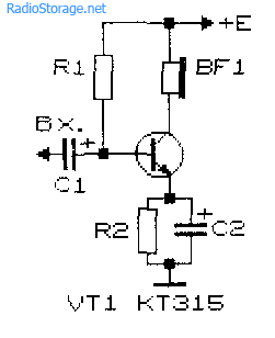
The simplest ULF, made according to a circuit with a common emitter, is shown in Fig. 1. A telephone capsule is used as a load. The permissible supply voltage for this amplifier is 3...12 V.
It is advisable to determine the value of the bias resistor R1 (tens of kOhms) experimentally, since its optimal value depends on the supply voltage of the amplifier, the resistance of the telephone capsule, and the transmission coefficient of a particular transistor.
Rice. 1. Circuit of a simple ULF on one transistor + capacitor and resistor.
To select the initial value of resistor R1, it should be taken into account that its value should be approximately one hundred or more times greater than the resistance included in the load circuit. To select a bias resistor, it is recommended to connect a constant resistor with a resistance of 20...30 kOhm and a variable resistor with a resistance of 100...1000 kOhm in series, after which, by applying a small amplitude audio signal to the input of the amplifier, for example, from a tape recorder or player, rotate the variable resistor knob to achieve the best signal quality at its highest volume.
The capacitance value of the transition capacitor C1 (Fig. 1) can range from 1 to 100 μF: the larger the value of this capacitance, the lower frequencies the ULF can amplify. To master the technique of amplifying low frequencies, it is recommended to experiment with the selection of element values and operating modes of amplifiers (Fig. 1 - 4).
Improved single-transistor amplifier options
More complicated and improved compared to the diagram in Fig. 1 amplifier circuits are shown in Fig. 2 and 3. In the diagram in Fig. 2, the amplification stage additionally contains a chain of frequency-dependent negative feedback (resistor R2 and capacitor C2), which improves the quality of the signal.
Rice. 2. Diagram of a single-transistor ULF with a chain of frequency-dependent negative feedback.

Rice. 3. Single-transistor amplifier with a divider to supply bias voltage to the base of the transistor.

Rice. 4. Single-transistor amplifier with automatic bias setting for the transistor base.
In the diagram in Fig. 3, the bias to the base of the transistor is set more “rigidly” using a divider, which improves the quality of operation of the amplifier when its operating conditions change. “Automatic” bias setting based on an amplifying transistor is used in the circuit in Fig. 4.
Two-stage transistor amplifier
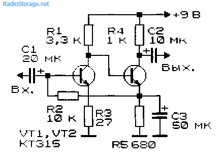
By connecting two simple amplification stages in series (Fig. 1), you can obtain a two-stage ULF (Fig. 5). The gain of such an amplifier is equal to the product of the gain factors of individual stages. However, it is not easy to obtain a large stable gain with a subsequent increase in the number of stages: the amplifier will most likely self-excite.

Rice. 5. Circuit of a simple two-stage low-frequency amplifier.
New developments of low-frequency amplifiers, the circuit diagrams of which are often presented on the pages of magazines in recent years, are aimed at achieving a minimum coefficient of nonlinear distortion, increasing output power, expanding the bandwidth of amplified frequencies, etc.
At the same time, when setting up various devices and conducting experiments, a simple ULF is often needed, which can be assembled in a few minutes. Such an amplifier must contain a minimum number of scarce elements and operate over a wide range of changes in supply voltage and load resistance.
ULF circuit based on field-effect and silicon transistors
The circuit of a simple low-frequency power amplifier with direct coupling between stages is shown in Fig. 6 [Rl 3/00-14]. The input impedance of the amplifier is determined by the rating of potentiometer R1 and can vary from hundreds of ohms to tens of megohms. You can connect a load with a resistance from 2...4 to 64 Ohms and higher to the amplifier output.
For high-resistance loads, the KT315 transistor can be used as VT2. The amplifier is operational in the range of supply voltages from 3 to 15 V, although its acceptable performance is maintained even when the supply voltage is reduced to 0.6 V.
The capacitance of capacitor C1 can be selected in the range from 1 to 100 μF. In the latter case (C1 = 100 μF), the ULF can operate in the frequency band from 50 Hz to 200 kHz and higher.
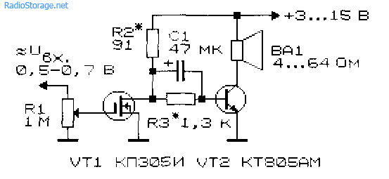
Rice. 6. Circuit of a simple low-frequency amplifier using two transistors.
The amplitude of the ULF input signal should not exceed 0.5...0.7 V. The output power of the amplifier can vary from tens of mW to units of W depending on the load resistance and the magnitude of the supply voltage.
Setting up the amplifier consists of selecting resistors R2 and R3. With their help, the voltage at the drain of transistor VT1 is set equal to 50...60% of the power source voltage. Transistor VT2 must be installed on a heat sink plate (radiator).
Track-cascade ULF with direct coupling
In Fig. Figure 7 shows a diagram of another seemingly simple ULF with direct connections between cascades. This kind of connection improves the frequency characteristics of the amplifier in the low-frequency region, and the circuit as a whole is simplified.

Rice. 7. Schematic diagram of a three-stage ULF with direct connection between stages.
At the same time, tuning the amplifier is complicated by the fact that each amplifier resistance has to be selected individually. Approximately the ratio of resistors R2 and R3, R3 and R4, R4 and R BF should be in the range (30...50) to 1. Resistor R1 should be 0.1...2 kOhm. Calculation of the amplifier shown in Fig. 7 can be found in the literature, for example, [R 9/70-60].
Cascade ULF circuits using bipolar transistors
In Fig. 8 and 9 show circuits of cascode ULFs using bipolar transistors. Such amplifiers have a fairly high gain Ku. Amplifier in Fig. 8 has Ku=5 in the frequency band from 30 Hz to 120 kHz [MK 2/86-15]. ULF according to the diagram in Fig. 9 with a harmonic coefficient of less than 1% has a gain of 100 [RL 3/99-10].

Rice. 8. Cascade ULF on two transistors with gain = 5.

Rice. 9. Cascade ULF on two transistors with gain = 100.
Economical ULF with three transistors
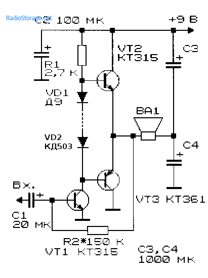
For portable electronic equipment, an important parameter is the efficiency of ULF. The diagram of such a ULF is shown in Fig. 10 [RL 3/00-14]. Here, a cascade connection of field-effect transistor VT1 and bipolar transistor VT3 is used, and transistor VT2 is connected in such a way that it stabilizes the operating point of VT1 and VT3.
As the input voltage increases, this transistor shunts the emitter-base junction of VT3 and reduces the value of the current flowing through transistors VT1 and VT3.

Rice. 10. Circuit of a simple economical low-frequency amplifier with three transistors.
As in the above circuit (see Fig. 6), the input resistance of this ULF can be set in the range from tens of ohms to tens of megohms. A telephone capsule, for example, TK-67 or TM-2V, was used as a load. The telephone capsule, connected using a plug, can simultaneously serve as a power switch for the circuit.
The ULF supply voltage ranges from 1.5 to 15 V, although the functionality of the device is maintained even when the supply voltage is reduced to 0.6 V. In the supply voltage range of 2... 15 V, the current consumed by the amplifier is described by the expression:
1(μA) = 52 + 13*(Upit)*(Upit),
where Upit is the supply voltage in Volts (V).
If you turn off transistor VT2, the current consumed by the device increases by an order of magnitude.
Two-stage ULF with direct coupling between stages
Examples of ULFs with direct connections and minimal selection of operating modes are the circuits shown in Fig. 11 - 14. They have high gain and good stability.

Rice. 11. Simple two-stage ULF for a microphone (low noise level, high gain).

Rice. 12. Two-stage low-frequency amplifier using KT315 transistors.
Rice. 13. Two-stage low-frequency amplifier using KT315 transistors - option 2.
The microphone amplifier (Fig. 11) is characterized by a low level of self-noise and a high gain [MK 5/83-XIV]. An electrodynamic type microphone was used as the VM1 microphone.
A telephone capsule can also act as a microphone. Stabilization of the operating point (initial bias at the base of the input transistor) of the amplifiers in Fig. 11 - 13 is carried out due to the voltage drop across the emitter resistance of the second amplification stage.

Rice. 14. Two-stage ULF with field-effect transistor.
The amplifier (Fig. 14), which has a high input resistance (about 1 MOhm), is made on a field-effect transistor VT1 (source follower) and a bipolar transistor - VT2 (with a common one).
A cascade low-frequency amplifier using field-effect transistors, which also has a high input impedance, is shown in Fig. 15.

Rice. 15. circuit of a simple two-stage ULF using two field-effect transistors.
ULF circuits for working with low-Ohm loads
Typical ULFs, designed to operate with low-impedance loads and having an output power of tens of mW and higher, are shown in Fig. 16, 17.

Rice. 16. A simple ULF for working with a low-resistance load.
Electrodynamic head BA1 can be connected to the output of the amplifier, as shown in Fig. 16, or diagonally to the bridge (Fig. 17). If the power source is made of two series-connected batteries (accumulators), the right output of the head BA1 according to the diagram can be connected to their midpoint directly, without capacitors SZ, C4.
Rice. 17. Circuit of a low-frequency amplifier with the inclusion of a low-resistance load in the diagonal of the bridge.
If you need a circuit for a simple tube ULF, then such an amplifier can be assembled even using one tube, look at our electronics website in the corresponding section.
Literature: Shustov M.A. Practical circuit design (Book 1), 2003.
Corrections in the publication: in Fig. 16 and 17, instead of diode D9, a chain of diodes is installed.
Other articles devoted to the construction of this ULF.
Schematic diagram of the power supply.

The power supply is assembled according to one of the standard schemes. Bipolar power supply is selected to power the final amplifiers. This allows the use of inexpensive, high-quality integrated amplifiers and eliminates a number of problems associated with supply voltage ripple and turn-on transients. https://site/
The power supply must provide power to three microcircuits and one LED. Two TDA2030 microcircuits are used as final power amplifiers, and one TDA1524A microcircuit is used as a volume control, network base and tone.
Electrical diagram of the power supply.

|
VD3... VD6 – KD226 |
C1 – 680mkFx25V C3... C6 – 1000mkFx25V |
A bipolar, full-wave rectifier with a midpoint is assembled using diodes VD3...VD6. This connection circuit reduces the voltage drop across the rectifier diodes by half compared to a conventional bridge rectifier, since in each half-cycle the current flows through only one diode.
Electrolytic capacitors C3...C6 are used as a rectified voltage filter.
The IC1 chip contains a voltage stabilizer to power the electronic volume, stereo and tone control circuits. The stabilizer is assembled according to a standard design.
The use of the LM317 chip is due only to the fact that it was available. Here you can use any integral stabilizer.
The protective diode VD2, indicated by a dotted line, is not necessary to use when the output voltage on the LM317 chip is below 25 Volts. But, if the input voltage of the microcircuit is 25 Volts or higher, and resistor R3 is a tuning resistor, then it is better to install a diode.
The value of resistor R3 determines the output voltage of the stabilizer. During prototyping, I soldered a trimmer resistor in its place, used it to set the voltage to about 9 Volts at the output of the stabilizer, and then measured the resistance of this trimmer so that I could install a constant resistor instead.
The rectifier feeding the stabilizer is made according to a simplified half-wave circuit, which is dictated by purely economic considerations. Four diodes and one capacitor are more expensive than one diode and one slightly larger capacitor.
The current consumed by the TDA1524A microcircuit is only 35mA, so this circuit is quite justified.
LED HL1 – amplifier power-on indicator. A ballast resistor for this indicator is installed on the power supply board - R1 with a nominal resistance of 500 Ohms. The LED current depends on the resistance of this resistor. I used a green LED rated at 20mA. When using a red LED type AL307 with a current of 5mA, the resistance of the resistor can be increased by 3-4 times.
Printed circuit board.

The printed circuit board (PCB) is designed based on the design of a specific amplifier and available electrical components. The board has only one hole for mounting, located in the very center of the PCB, which is due to its unusual design.

To increase the cross-section of copper tracks and save ferric chloride, the areas free from tracks on the PP were filled using the “Polygon” tool.
Increasing the width of the tracks also prevents peeling of the foil from the fiberglass laminate in the event of a violation of the thermal regime or during repeated re-soldering of radio components.

According to the drawing given above, a printed circuit board was made from foil fiberglass with a cross section of 1 mm.
To connect the wires to the printed circuit board, copper pins (soldiers) were riveted into the holes of the board.
This movie requires Flash Player 9 |
||
And this is the already assembled printed circuit board of the power supply.
To see all six views, drag the picture with the cursor or use the arrow buttons located at the bottom of the picture.
The mesh on the PP copper tracks is the result of using this technology. 
When the board is assembled, it is advisable to test it before connecting the final amplifiers and the regulator unit. To test the power supply, you need to connect an equivalent load to its outputs, as in the diagram above.
Resistors of the PEV-10 type at 10-15 Ohms are suitable as a load for the +12.8 and -12.8 Volt rectifiers.
It’s a good idea to look at the voltage at the output of a stabilizer loaded onto a resistor with a resistance of 100-150 Ohms with an oscilloscope to ensure there is no ripple when the alternating input voltage decreases from 14.3 to 10 Volts.
P.S. Refinement of the printed circuit board.
During commissioning, the printed circuit board of the power supply was damaged.

During modification, we had to cut one track, item 1, and add one contact, item 2, to connect the transformer winding that powers the voltage stabilizer.
The End Millenium is a high-end power amplifier with a power range from 99 to 300 watts (into 8 ohms). The use of high-quality class A/B amplifiers is achieved by a number of circuit solutions. First of all, attention is drawn to the absence of any feedback circuits, because Even if it corrects the error of the signal received at the input, after it it is no longer reversible. A simple circuit design, together with high quality components, ensures a short signal path from input to output. The use of high-tech components can be noted by the use of polypropylene capacitors, multi-emitter bipolar transistors and miniature resistors on a glass substrate.
The higher frequencies of the range are easily reproduced by the ultra-fast amplifier (linearity up to > 500,000Hz), and the use of a four-stage tunnel at the output gives the signature fast transmission of low frequencies. The overall scene is well detailed and transparent.
Schematic diagram of the The End Millennium amplifier:

The circuit diagram shows how simply the amplifier idea is implemented. Absence of feedback circuits (100% without feedback), absence of capacitors and other components that introduce distortion into the signal in the signal circuits. The frequency response is linear from DC to the maximum high-frequency signal - 500,000 Hz. This may be the fastest amplifier you've ever heard! Any part of the musical accompaniment, from the deepest bass to the smallest transitions, is transmitted by the amplifier with ease.
The amplifier board also contains additional features such as DC protection and output short circuit protection. The protection monitors the occurrence of any overload at the output and turns off the amplifier for a few seconds. No current or signal limitations are used. If an error is detected, the device automatically turns off and waits for the situation to normalize. It will then turn on and continue playing. This system is so effective that it allows the output to short circuit for several days!
Thanks to the new amplifier topology, which, in fact, in some respects breaks the generally accepted principles, it has become possible to build an amplifier with a well-controlled sound picture, a moving stage with a high degree of detail, at a very affordable price. The low cost is achieved mainly by the fact that you do the assembly yourself.
The four-stage tunnel output stage allows you to accurately transmit the amplified signal from the source to the sound head membrane. Not only start the movement of the membrane, but also stop it in a microsecond.
100% no OS = 100% musicality
The soft, almost intimate sound is mainly due to the amplifier's circuit design, which does not contain the usual feedback circuit in such cases. This design principle is usually called 100% no feedback and is also used in the designs of other brands of high-end amplifiers (usually very expensive).
In conventional amplifiers (with a feedback circuit), the typical approach is to use circuits with large gains (Kus up to 100,000) and a high degree of signal distortion in order to achieve the required voltage gain. By comparing the shape of the output signal with respect to the input signal, it is possible to correct the transmission error and thus reduce the measured harmonic distortion. However, such an error cannot be corrected until it is detected and reproduced by the sound head, which is also connected to the distorted signal. This can be compared to an attempt to suppress waves in a swimming pool by creating the same waves in antiphase. Not practical, and the waves are too low in frequency to match the time required to reach the corrective waves on the other side of the pool.
Another problem arises when you try to linearize a signal that has been amplified by a nonlinear (signal-distorting) element. Inevitable modulation occurs, previously called intermodulation signal distortion. This annoying misunderstanding can be described as if two vocalists are singing at the same time, and you hear a third, inharmonious, annoying tone. At best, this can be eliminated by losing the frequency range, but it is still a loss. Another way to hear intermodulation distortion in a conventional amplifier is by turning the signal volume up or down.
Millennium reproduces the signal regardless of the volume level and dynamic range. It uses a completely different principle for correcting distortion. In non-OS circuits, it is impossible to get rid of distortions once they have already occurred, so all measures are taken to prevent their occurrence. Ultra linear semiconductors, high stability resistors, no capacitors and looped PCB traces for all audio signal circuits. All components used in the design are of the highest quality from recognized market leaders, which can also only be found in high-quality amplifiers in an exorbitant price range.
The result is a circuit that is not overloaded with complexity and clear sound without modulation, but with good detail and musical dynamics.

The English-made Z-transistor is a bipolar vertical transistor created using technology usually applied to the production of MOSFET transistors. However, it has a significantly lower junction resistance (Re or Rs) than a FET or MOSFET and therefore introduces less distortion into the signal.
Low junction capacitance (6 pF) and very low noise figure are also advantages.
Millennium High Voltage Circuits
Initially, the Millennium was conceived as an amplifier with a power of 120 Watts into a load of 8 Ohms or 240 Watts into a load of 4 Ohms with a transformer supply of 33-0-33 Volts. But by adding additional output stage modules you can use it at higher powers or lower load resistances (down to 1 Ohm). When powering the amplifier 40-0-40: one additional module provides 180 Watts into an 8 Ohm load, two modules provide 350 Watts into a 4 Ohm load. With a power supply of 50-0-50 Volts: three modules - 250 Watts at 8 Ohms, 500 Watts at 4 Ohms.
The add-on module parts are placed on a separate board, which also contains emitter resistors and associated bypass capacitors to ensure stage stability.
An increase in output power is also possible by reducing the load resistance when powered at 33-0-33 Volts, more than 800 Watts at a load of 1 Ohm.
To avoid loss of quality, it is not recommended to use additional modules at the output of devices that will be designed to reproduce high-frequency and mid-range frequencies. A parallel module will inevitably have differences in the characteristics of the transistors, which will lead to the appearance of higher harmonics in the signal, manifesting itself as an aggressive sound at high signal volumes. A solution may be to use separate outputs for the LF and MF/HF channels. Although this will require speakers with separate channels, most modern loudspeakers have this option. In this case, one output channel will be loaded onto the mid/high frequency section, and a number of additional modules will be loaded onto a more powerful bass output, where higher harmonics will be cut off by the speaker input filter.
Separate output connectors are standard on our 180 Watt and larger sets. (Except for balanced input versions where parallel output stages are not used in any case)

Additional output module board with emitter resistors and blocking capacitors - up to three boards at a time. They are connected to the main board with power and input/output signal wires.
“The End” is the most successful audio design in Scandinavia!
Any Scandinavian radio amateur knows the previous version 3.1 design. More than 3,600 of these DIY kits were sold between 1995 and 1999 until the Millennium. Almost all of them now work in hundreds of different audio systems, confirming the unusually high quality of reproduction.
In the Millennium version it is improved in all aspects:
Four-stage output tunnel bass pumping
Glass backed resistors for better linearity and uniformity
Signal amplification with specially designed Z-transistors with very low Re and output capacitance (Сс=6 pF).
Low signal distortion due to ultra linear core topology.
High frequency detailing through the use of 4.7 mF blocking capacitors with a polypropylene separator on the power buses.
All PCB traces related to the audio signal have rounded vias. This prevents the occurrence of standing waves and promotes more accurate and correct reproduction.
In addition, several additional functions have been added to the compact board, made of high-quality Fr4 fiberglass. The switchable protection function will react to the appearance of a constant voltage at the output of 5 mV, and effective short-circuit protection will preserve your amplifier even under extreme overloads.
The bias system, subject to temperature conditions for supply voltages of +/- 100 Volts, ensures long-term operation in any application. Millennium is also stable when powered down to +/- 10 Volts.

Nutritional Considerations
Amplifier power supply is very critical for playback quality!
If you are planning to build the perfect power supply for an amplifier, the most attractive would be to use a bank of (Swedish) RIFA capacitors from 100,000 uF each. Add blocking inductors to reduce charging currents and you have the best power supply for an audio system.
However, the price and size of the installation with this approach make it less attractive. It's too expensive and will take up about the same amount of space as a small refrigerator. Therefore, we have developed a "Super-Duper" Power Supply that is more rationally designed than the bulky but simple solution from RIFA.
120,000 µF of American low-impedance capacitors from ChemiCon are allocated to separately power the high-power and sensitive signal stages, so any power dips caused by overloading the power stages will not affect the input and driver circuits.
In addition, a set of polycarbonate capacitors helps reduce high-frequency noise from the rectifier.

These two 4.7 mF capacitors are marked on the board, but are now mounted on the amplifier board rather than the power supply.
AUX output is used to power the voltage amplifier and drivers.

A capacity reserve of 120,000 uF ensures complete stability and sufficient power to power even critical loads. The ChemiCon brand was formerly known as Sprague.
Complete The End Millenium Amplifier Circuit

Scale Not 1:1
Board size: 107x54mm
Photo of the amplifier board

"Hatsink placed here" - Radiator installation location
"BIAS Testpoint" - Bias setting test point

Assembly instructions
Assembly of the Millennium is not difficult and does not take much time.
Start by emptying all the parts from the bag onto the table.
Heat up the soldering iron.

Start by installing low-profile components such as resistors and trimmers. Check the numbering of elements on the diagram with that written on the board itself and compare with the color code printed in the table on the previous page. If you are sure that everything is installed correctly, proceed to soldering. After this, install capacitors, first small ones, then larger ones. Solder it.
Two 470 mF electrolytes are installed on the opposite side; do not confuse the polarity; the strip indicating minus on both faces the near edge of the board.
Install them onto the board before cutting the leads and soldering them.
Now install the T9 and drivers (be careful, they are installed on their own side) as high as the length of the leads allows. They must be at the correct angle to the board.
After this, screw the drivers onto the heatsink using short 3mm screws and small spacers. No grease is allowed on them and they must fit tightly to the gasket without an air gap. The picture shows that 4m7 capacitors are also already installed, but it will be a little easier if you wait.
Place a thermal pad over the output transistor mounting location and install cardboard washers under the mounting screws. The use of lubricants is not permitted!
Secure each Sanken to the CORRECT place on the board, with the metal backing to the spacer. Make sure that there are no foreign matter (chips, dirt) under the gasket. Use a larger spacer and screws. Tighten the screws as tightly as possible without tearing them off.
Then solder them to the board and trim the leads.
Now install the 4.7 mF capacitors on the back of the board. Solder the input and output conductors as shown in the pictures.
ATTENTION!
If you use a "Super-Duper" power supply with separate transformers for the input stages and driver (recommended), do not forget to cut the conductors on the printed circuit board between + and Aux+, as well as - and Aux-

Connecting input connectors (unbalanced and balanced, respectively)


Connecting additional modules to the main board

Settings
Connect a multimeter (mV) between two test points on the board, see page 10.
Apply power to the amplifier, DO NOT connect the load yet.
Set the bias adjustment trimmer resistor (501) to 10 mV if you use an amplifier with an 8 Ohm load or 20 mV at 4 Ohms.
Connect a multimeter to the output terminals of the amplifier. Set the DC component adjustment trimmer resistor (103) as close to zero as possible. Deviations of +/- 50 mV are within tolerance when using any speakers.
Check the bias voltage again; it may need to be adjusted. The parameter deviation +/- 20% of the value is within the tolerance.
Repeat the procedures for the other channel. If voltages differ from those listed, please contact LC Audio before proceeding.
Connect your speakers to your amplifier and start playing! You must understand that it takes 1-2 weeks of running in the amplifier to enter operating mode.

Using DC output voltage protection
The Millennium has built-in DC output voltage protection, which you can use at your discretion. You can disable it or exclude it from the scheme altogether if you wish. Some recommendations on this matter:
Some experts are inclined to believe that the protection circuit affects the transmission of low frequencies. And in some cases they are right. The bass becomes softer and more diffuse. This happens because the protection in some amplifiers operates at input filter cutoff frequencies much higher than necessary, say 10-20Hz.
Millennium protection, thanks to our efforts, does not affect the bass section, because the filter cutoff frequency is below 0.5 Hz and a second order filter is installed instead of the usual first order for such cases. This means that the filter cutoff characteristic is steeper, and there is practically no effect on the audio signal (at 20 Hz the filter effect is close to zero)
Filter capacitors C12 and C14 are made in plastic cases and with non-magnetic leads, so that if the entire frequency range of the signal passes through them, they will withstand any, the most demanding audio test. However, a signal above 0.5 Hz does not pass through them.
It is necessary to use a protection system if you use electrostatic speakers, since their DC resistance is close to zero.
You may NOT need to use the protection system if you are using conventional dynamic systems, as some will allow up to 200mV of constant input voltage without damage.
*The name of the topic on the forum must correspond to the form: Article title [article discussion]
An audio frequency amplifier (AFA), or low frequency amplifier (LF) is one of the most common electronic devices. We all receive sound information using one or another type of ULF. Not everyone knows, but low-frequency amplifiers are also used in measurement technology, flaw detection, automation, telemechanics, analog computing and other areas of electronics.
Although, of course, the main use of ULF is to bring a sound signal to our ears using acoustic systems that convert electrical vibrations into acoustic ones. And the amplifier must do this as accurately as possible. Only in this case do we receive the pleasure that our favorite music, sounds and speech give us.
From the advent of Thomas Edison's phonograph in 1877 to the present, scientists and engineers have struggled to improve the basic parameters of the ULF: primarily for the reliability of the transmission of sound signals, as well as for consumer characteristics such as power consumption, size, ease of manufacture, configuration and use.
Beginning in the 1920s, a letter classification of classes of electronic amplifiers was formed, which is still used today. Classes of amplifiers differ in the operating modes of the active electronic devices used in them - vacuum tubes, transistors, etc. The main “single-letter” classes are A, B, C, D, E, F, G, H. Class designation letters can be combined in case of combining some modes. The classification is not a standard, so developers and manufacturers can use letters quite arbitrarily.
Class D occupies a special place in the classification. The active elements of the ULF output stage of class D operate in a switching (pulse) mode, unlike other classes, where the linear mode of operation of the active elements is mostly used.
One of the main advantages of Class D amplifiers is the coefficient of performance (efficiency) approaching 100%. This, in particular, leads to a reduction in the power dissipated by the active elements of the amplifier, and, as a consequence, to a reduction in the size of the amplifier due to the reduction in the size of the radiator. Such amplifiers place significantly lower demands on the quality of the power supply, which can be unipolar and pulsed. Another advantage can be considered the possibility of using digital signal processing methods and digital control of their functions in class D amplifiers - after all, it is digital technologies that prevail in modern electronics.
Taking into account all these trends, the Master Kit company offers wide selection of class amplifiersD, assembled on the same TPA3116D2 chip, but having different purposes and power. And so that buyers do not waste time searching for a suitable power source, we have prepared amplifier + power supply kits, optimally suited to each other.
In this review we will look at three such kits:
- (D-class LF amplifier 2x50W + power supply 24V / 100W / 4.5A);
- (D-class LF amplifier 2x100W + power supply 24V / 200W / 8.8A);
- (D-class LF amplifier 1x150W + power supply 24V / 200W / 8.8A).

First set Designed primarily for those who need minimal dimensions, stereo sound and a classic control scheme in two channels simultaneously: volume, low and high frequencies. It includes and.

The two-channel amplifier itself has unprecedentedly small dimensions: only 60 x 31 x 13 mm, not including control knobs. Dimensions of the power supply are 129 x 97 x 30 mm, weight – about 340 g.
Despite its small size, the amplifier delivers an honest 50 watts per channel into a 4 ohm load at a supply voltage of 21 volts!
The RC4508 chip, a dual specialized operational amplifier for audio signals, is used as a pre-amplifier. It allows the amplifier input to be perfectly matched to the signal source, and has extremely low nonlinear distortion and noise levels.

The input signal is supplied to a three-pin connector with a pin pitch of 2.54 mm, and power supply and speaker systems are connected using convenient screw connectors.

A small heatsink is installed on the TPA3116 chip using heat-conducting glue, the dissipation area of which is quite sufficient even at maximum power.
Please note that in order to save space and reduce the size of the amplifier, there is no protection against reverse polarity of the power supply connection (reversal), so be careful when supplying power to the amplifier.
Taking into account its small size and efficiency, the scope of application of the kit is very wide - from replacing an outdated or broken old amplifier to a very mobile sound reinforcement kit for dubbing an event or party.
An example of using such an amplifier is given.
There are no mounting holes on the board, but for this you can successfully use potentiometers that have fastenings for a nut.
Second set includes two TPA3116D2 chips, each of which is enabled in bridged mode and provides up to 100 watts of output power per channel, as well as with an output voltage of 24 volts and a power of 200 watts.

With the help of such a kit and two 100-watt speaker systems, you can sound a major event even outdoors!
The amplifier is equipped with a volume control with a switch. A powerful Schottky diode is installed on the board to protect against polarity reversal of the power supply.

The amplifier is equipped with effective low-pass filters, installed in accordance with the recommendations of the manufacturer of the TPA3116 chip, and together with it, ensuring high quality of the output signal.
The supply voltage and speaker systems are connected using screw connectors.

The input signal can be supplied either to a three-pin connector with a pitch of 2.54 mm, or using a standard 3.5 mm Jack audio connector.

The radiator provides sufficient cooling for both microcircuits and is pressed against their thermal pads with a screw located at the bottom of the printed circuit board.
For ease of use, the board also has a green LED indicating when the power is turned on.
The dimensions of the board, including capacitors and excluding the potentiometer knob, are 105 x 65 x 24 mm, the distances between the mounting holes are 98.6 and 58.8 mm. Dimensions of the power supply are 215 x 115 x 30 mm, weight about 660 g.
Third set represents l and with an output voltage of 24 volts and a power of 200 watts.

The amplifier provides up to 150 watts of output power into a 4 ohm load. The main application of this amplifier is to build a high-quality and energy-efficient subwoofer.
Compared to many other dedicated subwoofer amplifiers, the MP3116btl excels at driving large-diameter woofers. This is confirmed by customer reviews of the ULF in question. The sound is rich and bright.
The heatsink, which occupies most of the printed circuit board area, ensures efficient cooling of the TPA3116.

To match the input signal at the amplifier input, the NE5532 microcircuit is used - a two-channel low-noise specialized operational amplifier. It has minimal nonlinear distortion and wide bandwidth.
The input signal amplitude regulator with a slot for a screwdriver is also installed at the input. With its help, you can adjust the volume of the subwoofer to the volume of the main channels.

To protect against supply voltage reversal, a Schottky diode is installed on the board.
Power and speaker systems are connected using screw connectors.
The dimensions of the amplifier board are 73 x 77 x 16 mm, the distances between the mounting holes are 69.4 and 57.2 mm. Dimensions of the power supply are 215 x 115 x 30 mm, weight about 660 g.
All kits include MEAN WELL switching power supplies.

Founded in 1982, the company is the world's leading manufacturer of switching power supplies. Currently, MEAN WELL Corporation consists of five financially independent partner companies in Taiwan, China, the USA and Europe.
MEAN WELL products are characterized by high quality, low failure rates and long service life.
Switching power supplies, developed on a modern element base, meet the highest requirements for the quality of output DC voltage and differ from conventional linear sources in their light weight and high efficiency, as well as the presence of protection against overload and short circuit at the output.
The LRS-100-24 and LRS-200-24 power supplies used in the presented kits have an LED power indicator and a potentiometer for precise adjustment of the output voltage. Before connecting the amplifier, check the output voltage and, if necessary, set its level to 24 volts using a potentiometer.
The sources used use passive cooling, so they are completely silent.
It should be noted that all the amplifiers considered can be successfully used to design sound reproduction systems for cars, motorcycles and even bicycles. When powering amplifiers with a voltage of 12 volts, the output power will be slightly less, but the sound quality will not suffer, and the high efficiency allows you to effectively power the ULF from autonomous power sources.
We also draw your attention to the fact that all the devices discussed in this review can be purchased individually and as part of other kits on the website.